background image


SolarSheat and Interior Wall Fan Assembly Manual Version 1.5


4


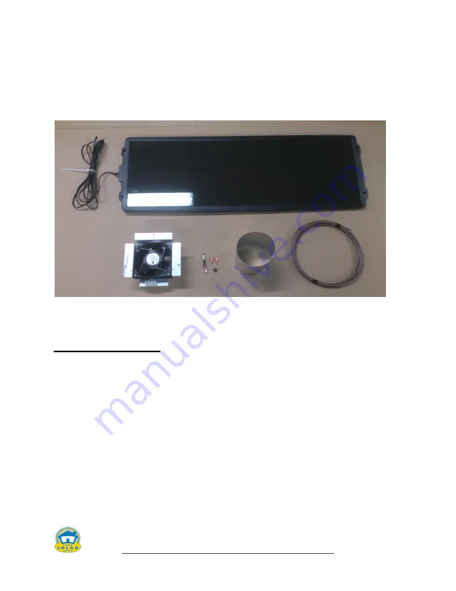
The SolarSheat wall installation system ships with a framed 12 V - 15W PV amorphous 
module with 11.5 ft wiring harness, fan plate with 12 volt – 15 W DC brushless fan 
attached, wiring harness, sensor, 5” round snap lock duct, grommet, two terminal 
connectors, hardware for assembling and power adapter attached.  These components also 
ship inside the new SolarSheat Fan Duct Kit. 


You will need to unpack the separate Sun Force PV cell.  Mounting hardware is provided 
for attaching the PV cell to a wall or roof.   

About this manual 

There are three steps to successful installation of the SolarSheat. 

They are:  

Step 1 – Drilling the holes and preparing for the wall for installation of the SolarSheat 

Step 2 – Installation of the fan assembly  

Step 3 – Installing the SolarSheat collector.  


Summary of Contents for SolarSheat

Page 1: ...alled in accordance to all local building plumbing electrical and safety codes Your Solar Home YSH does not warranty any installations that are not performed by an authorized YSH dealer installer YSH...

Page 2: ...usehold air by circulating it through the collector refer to the figure 1 1 below for a typical single panel wall mounted configuration The GS series collectors are modular and can be connected togeth...

Page 3: ...thermal energy on a clear and sunny day Measured for single collector setup results may vary depending on collector arrangement and fan choice Refer to Figures 1 2 to 1 5 for collector performance da...

Page 4: ...hardware for assembling and power adapter attached These components also ship inside the new SolarSheat Fan Duct Kit You will need to unpack the separate Sun Force PV cell Mounting hardware is provide...

Page 5: ...Jig Saw Measuring Tape Level Wire Cutters Fish Tape Pliers for crimping Robertson 2 screw bit 3 16 hex head driver for attaching the Tek screws to the mount hex head driver for securing the white head...

Page 6: ...ocate un shaded portion of the building for collector placement 2 Using a level and the included template mark the location of the bottom mounting rail and intake exhaust duct locations Be sure to avo...

Page 7: ...assembly plate on the inside wall of where you want the exhaust and heat The fan assembly can be installed on any outside wall For roof or ceiling mounts continue to use our DC inline fan part 1015 A...

Page 8: ...template of the tab or else you won t have any wall to mount the plate That is going to be where the plate ends and the tab is inserted in the wall 2 Use a pencil to mark each tab and where the bend i...

Page 9: ...l before the holes were drilled in the wall Remember the plate will cover the rough edges of the hole and cutout so you won t see any of the edges Use a vacuum to remove the debris from the wall Note...

Page 10: ...your inside wall Cut with shears There is a 10 inch piece provided 4 Trim the snap lock and insert the grommet to the desired size and drill a hole with a 21 64 drill bit or something close to the siz...

Page 11: ...roves you have a proper connection Connect the sensor by pushing on the two terminal strips together 7 Inserting the Fan Assembly Into the Wall Position the fan assembly into the wall Some positioning...

Page 12: ...fan assembly with the screws provided Make sure you have a clean 5 hole on the opposite side of the wall In this case siding is the actual wall See below 8 Attaching the collar Attach the 5 inch colla...

Page 13: ...e collar You can see the power harness on the left side and the sensor harness in the middle of the duct If required the snap lock can also be positioned from the outside wall to fit correctly over th...

Page 14: ...m support rail to the wall screws not provided ensure all wall penetrations are well sealed to prevent leaks Be sure to use the correct fastener type and size to match the wall construction and to car...

Page 15: ...tool or pliers and crimp the outside edges of the backdraft damper so it can fit into the collar Fit the collar with backdraft damper inside on the bottom intake Note The backdraft damper can also be...

Page 16: ...Secure the collector to the bottom rail one at a time and secure the collectors to each other if installing a 2 PAK or multiple collectors Run bead of silicone between the collar gasket and the wall t...

Page 17: ...r This will allow the sensor to work properly Important The Installation of the Fan Assembly Step 2 will need to be completed before you install the collector on the mounts so that you can attach the...

Page 18: ...cone on the upper edge of the top mounting rail to prevent water running down the back side of the collector Run bead of silicone to prevent water leakage behind the collector and around Run bead of s...

Page 19: ...collector on the inside of the mount or outside If you place the collector on the inside it will act as a cap It is snug fit when used this way See below 6 Installing the thermostat to the inside wal...

Page 20: ...inside of the thermostat can be clipped for Celsius display see thermostat manual Put the batteries inside the thermostat and gently snap the unit two pieces together Turn on the thermostat and set y...

Page 21: ...ote There will not be a fan assembly plate to secure the bottom diffuser to the wall You will need to mark the holes and then install the white hex screws and wall plugs provided to secure the diffuse...

Page 22: ...Sheat and Interior Wall Fan Assembly Manual Version 1 5 22 You have now completed the installation of the SolarSheat and interior wall fan assembly Congratulations on years of free heat with solar hea...

Reviews: