19
YT-1000/1050 series
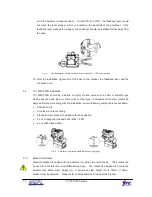
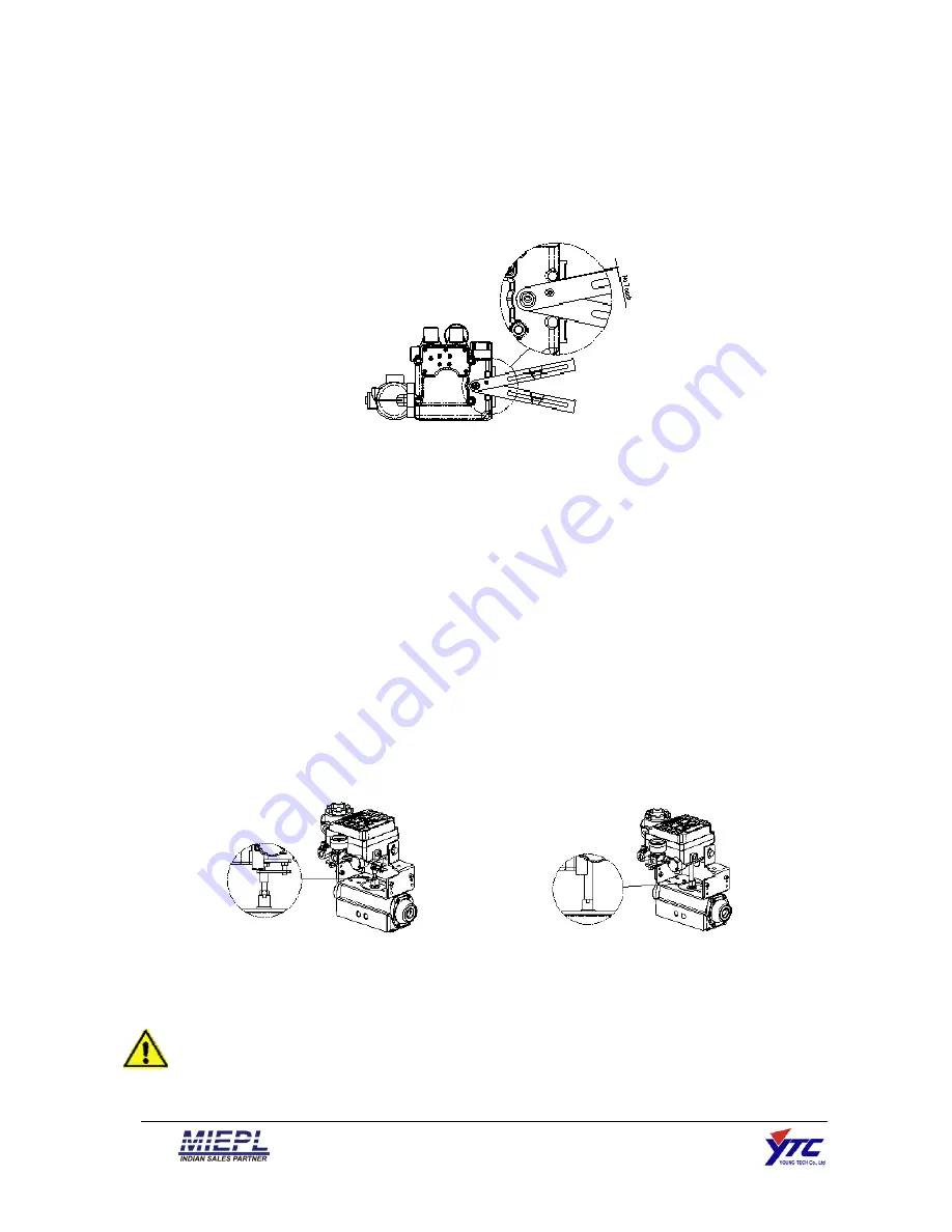
air to the actuator (manual position). On both 0% and 100%, the feedback lever should
not touch the lever stopper, which is located on the backside of the positioner. If the
feedback lever touches the stopper, the positioner should be installed further away from
the yoke.
Fig. 4:
Feedback lever should not touch lever stopper 0% ~ 100% valve stroke.
10. After the installation, tighten all of the bolts on the bracket, the feedback lever, and the
connection pin.
3.3
YT-1000/1050R Installation
YT-1000/1050R should be installed on rotary motion valve such as ball or butterfly type
which uses rack and pinion, scotch yoke or other type of actuators which stem rotates 90
degrees. Before proceeding with the installation, ensure following components are available.
Positioner unit
Fork lever and lever spring
Standard rotary bracket (included with the positioner)
4 pcs x hexagonal headed bolts (M8 x 1.25P)
4 pcs x M8 plate washer
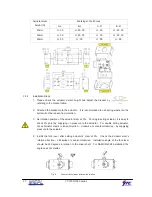
Fig. 5: Fork lever type (left) and NAMUR lever type (right)
3.3.1
Bracket information
Standard bracket (included with the positioner) contains two components. The bracket can
be used for both fork lever and NAMUR lever type. The bracket is designed to fit onto the
actuator with 20mm stem height (H). If actuator’s stem height (H) is 30mm or 50mm,
bracket must be adjusted. Please refer to below table how to adjust the bracket.
Summary of Contents for YT-1000L
Page 1: ...Electro Pneumatic Positioner PRODUCT MANUAL YT 1000 1050 SERIES VERSION 1 01...
Page 7: ...7 YT 1000 1050 series 2 4 2 YT 1000R...
Page 8: ...8 YT 1000 1050 series 2 4 3 YT 1050...
Page 11: ...11 YT 1000 1050 series 2 6 Parts and Assembly 2 6 1 YT 1000 1050L 2 6 2 YT 1000 1050R...
Page 12: ...12 YT 1000 1050 series 2 6 3 YT 1000L SPTM Internal 2 6 4 YT 1000R SPTM Internal...
Page 13: ...13 YT 1000 1050 series 2 6 5 YT 1000R L S Internal 2 6 6 YT 10000R SPTM L S Internal...
Page 16: ...16 YT 1000 1050 series 2 7 8 YT 1050L 2 7 9 YT 1050R...


