background image

13 

YT-3300/3301 series 


3. Installation 

3.1 Safety


When installing a positioner, please ensure to read and follow safety instructions.   

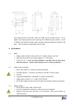
  Any input or supply pressures to valve, actuator, and / or to other related devices must 

be turned off. 


  Use bypass valve or other supportive equipment to avoid entire system “shut down”. 


  Ensure there is no remaining pressure in the actuator. 


3.2 YT-3300/3301L 

Installation


YT-3300/3301L should be installed on linear motion valves such as globe or gate type which 

uses spring return type diaphragm or piston actuators.  Before proceeding with the 

installation, ensure following components are available.   

 Positioner 

unit


  Feedback lever and lever spring


  Flange nut (bottom side of YT-3300/3301L)


  4 pcs x hexagonal headed bolts (M8 x 1.25P)


  4 pcs x M8 plate washer


3.2.1 Installation 

Steps


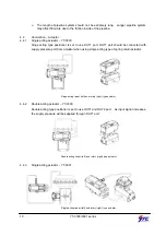
1.  Proper bracket must be made in order to adapt the positioner on the actuator yoke.  

Please consider following important points when a bracket is being designed. 


  Positioner’s feedback lever must be parallel to the ground at 50% of the valve stroke. 


  Feedback lever connection with the pin of the actuator clamp should be installed in 

such a way that the valve stroke length coincides with the corresponding figure in 

“mm” marked on the feedback lever.    Improper setting may cause poor linearity and 

may create unnecessary hunting during the operation.


2.  Assemble the positioner with the bracket made in previous step by fastening the bolts.   

Please refer to the backside of the positioner for size of the bolts.  The standard bolt 

size is M8 x 1.25P.    Please contact Young Tech Co., Ltd for other bolt sizes.   


YT-3300L 

     YT-3301L 

Summary of Contents for YT-3300 Series

Page 1: ...SMART POSITIONER PRODUCT MANUAL YT 3300 3301 SERIES VERSION 1 02...

Page 2: ...3 1 Safety 13 3 2 YT 3300 3301L Installation 13 3 2 1 Installation Steps 13 3 3 YT 3300L Direct Mounting Installation 15 3 3 1 Installation Steps 15 3 4 YT 3300R Installation 16 3 4 1 Bracket Informa...

Page 3: ...4 Hand Calibration Mode HAND CAL 27 6 3 4 1 Zero Point PV_ZERO and End Point PV_END for Valves 27 6 3 4 2 Zero Point TR_ZERO and End Point TR_END for Transmitter 27 6 3 4 3 End Point Ratio for Valve...

Page 4: ...4 YT 3300 3301 series 7 2 Warning Code 33 8 Main Software Map 35...

Page 5: ...uth Korea 1 2 Manufacturer Warranty For the safety it is important to follow the instructions in the manual Manufacturer will not be responsible for any damages caused by user s negligence Manufacture...

Page 6: ...ce and optimize operating conditions Valve system feedback is greatly improved by the accuracy and fast response of the YT 3300 Different valve characteristics can be adjusted Linear Quick Open Equal...

Page 7: ...7 YT 3300 3301 series 2 4 Product Number YT 3300 series can be used for direct mounting application YT 3301 standard cable length is 5 meters Maximum cable length is 20 meters...

Page 8: ...nsor Temp 40 120 Linearity 0 5 F S cable length 5 m Hysteresis 0 5 F S cable length 5 m Sensitivity 0 2 F S cable length 5 m Repeatability 0 3 F S cable length 5 m Flow Capacity 70 LPM Sup 0 14 MPa Ai...

Page 9: ...9 YT 3300 3301 series 2 6 Parts and Assembly YT 3300L YT 3300R YT 3300L series exploded view YT 3300R series exploded view...

Page 10: ...10 YT 3300 3301 series 2 7 Parts and Assembly YT 3301L YT 3301R 2 8 Product Dimension 2 8 1 YT 3300L...

Page 11: ...11 YT 3300 3301 series 2 8 2 YT 3300R 2 8 2 1 YT 3300R standard 2 8 2 2 YT 3300R with L S option...

Page 12: ...12 YT 3300 3301 series 2 8 3 YT 3301L 2 8 4 YT 3301R...

Page 13: ...3301L 4 pcs x hexagonal headed bolts M8 x 1 25P 4 pcs x M8 plate washer 3 2 1 Installation Steps 1 Proper bracket must be made in order to adapt the positioner on the actuator yoke Please consider fol...

Page 14: ...d be inserted when the actuator clamp is at 50 of the total valve stroke Proper way to connect feedback lever connection pin and lever spring YT 3300 and YT 3301 sensor 7 Check if feedback lever is pa...

Page 15: ...tioner should be installed further away from the yoke Feedback lever should not touch lever stopper 0 100 valve stroke 10 After the installation tighten all of the bolts on the bracket the feedback le...

Page 16: ...other type of actuators which stem rotates 90 degrees Before proceeding with the installation ensure following components are available Positioner unit Fork lever and lever spring Standard rotary bra...

Page 17: ...tested positioner s operation with any other gases other than clean air Please contact Young Tech Co Ltd for any questions 4 2 Supply Pressure Condition Dry air with at least 10 lower than ambient te...

Page 18: ...d be connected with supply pressure port from actuator when using single acting type of spring return actuator Singe acting linear left and rotary right type actuator 4 4 2 Double acting actuator YT 3...

Page 19: ...ver when the power is still alive Please use ring type rug to protect against vibration or any other external impact Positioner with PTM options must be supplied 10 28V DC separately For L S option se...

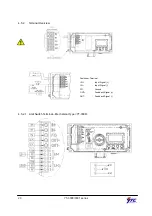
Page 20: ...0 YT 3300 3301 series 4 5 2 Terminal Overview Positioner Terminal IN Input Signal IN Input Signal FG Ground OUT Feedback Signal OUT Feedback Signal 4 5 2 1 Limit Switch Terminal Mechanical Type YT 330...

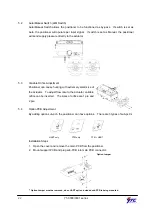
Page 21: ...sure that the resistance is less than 100ohm 3 When using external ground use screw driver to unscrew the ground bolts Insert outside ground bolts and spring washer into ring type terminal of the gro...

Page 22: ...e hunting with extremely small size of the actuator To adjust flow rate to the actuator variable orifice can be inserted The sizes of orifice are 1 pie and 2 pie 5 4 Option PCB Adjustment By adding op...

Page 23: ...Mode will be appeared on positioner s LCD screen within 6 seconds RUN indicates that the positioner adjusts the valve stroke according to the receiving signal There are six types of display message in...

Page 24: ...O X It is recommend to perform AUTO2 calibration for initial positioner setting 6 3 1 1 AUTO1 Calibration AUTO1 AUTO1 changes zero and end points however KP KI KD will not be adjusted It is recommende...

Page 25: ...ptimized Hunting or oscillation can be prevented by adjusting parameter values Once parameter values have been changed the changed values are being affected as soon as you save the value To save the c...

Page 26: ...the percentage of error allowance As the value increase it is more likely to have hunting As the value decreases it can have poor linearity 6 3 3 4 I value KI I value indicates the additional compensa...

Page 27: ...d End Point PV_END for Valves PZ_ZERO adjusts the zero point of the valve and PV_END adjusts the end point of the valve 6 3 4 2 Zero Point TR_ZERO and End Point TR_END for Transmitter TR_ZERO adjusts...

Page 28: ...back Signal TR_NORM REV The feedback signal from the positioner can be viewed as normal or as reverse 6 3 4 5 Normal Reverse HART Signal HT_NORM REVS HART signal from the positioner can be viewed as n...

Page 29: ...Action RA 6 3 5 2 Characteristic Adjustment CHAR The valve characteristic can be set on the field s requirement There are 3 types of characteristics linear LIN equal percentage EQ and quick open QO D...

Page 30: ...Open allows the valve to open completely as the input signal reaches around 20mA 6 3 5 5 Tight Shut Close TSHUT CL Tight Shut Close allows the valve to close completely as the input signal reaches ar...

Page 31: ...et any specific point as end position For example the end point can be set at input signal of 11mA The difference between zero and end point must be greater or equal to 4mA 6 3 5 9 Interpolation Mode...

Page 32: ...is at 25 bIAS 75 BIAS value when valve position is at 75 0Y 0d Total used time duration If a unit was used less than 1 minute the time will not accumulate FULL_OP Time elapsed for valve to fully open...

Page 33: ...ressure level RNG ERR Operating angle is too small due to improper positioner installation Adjust bracket so the positioner can be mounted closer to actuator C Error of 10 or more persists more than 1...

Page 34: ...ner Ensure the feedback lever does not touch the lever stopper at 0 and 100 After re installation perform AUTO1 H Pv is over 4000 The angle of feedback lever is too large Re install the positioner Ens...

Page 35: ...35 YT 3300 3301 series 8 Main Software Map...

Page 36: ...series Manufacturer Young Tech Co Ltd 3022 Hagun ri Yangchon myeon Kimpo si Kyeonggi do 415 843 South Korea Tel 82 31 986 8545 Fax 82 31 986 2683 Email ytc ytc co kr Copyright Young Tech Co Ltd All R...

Reviews: