- 8 -
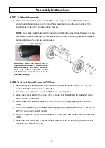
STEP 1: Wheel Assembly
1. Attach both wheels (#48) to the oil tank (#51) secure using flat washer Ø20 (#47), thin hex
slotted nut (#46) and cotter pin 4x36 (#45). Place plastic bushing on the axle cap (#44) then
install the axle cap on the end using rubber hammer.
NOTE:
Use a black plastic bushing to fix the axle cap (#44) like below picture. Please cover the
black bushing onto the axle cap, and use rubber/wooden hammer knocking the end of the plastic
bushing and make the axle cap fixed on wheel.
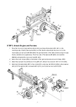
STEP 2: Attach Main Frame to Oil Tank
1. Assemble the tow bar (#23) and support leg (#14) together using hex bolt M10x75 (#15), flat
washer Ø10 (#8) and nylon lock nut M10 (#5).
2. Insert the lock pin (#16) into the tow bar (#23) and support leg (#14).
3. Attach the tow bar (#23) to the oil tank (#51) using hex bolt M12x80 (#2), flat washer Ø12 (#3)
and nylon lock nut M12 (#4).
4. Attach one side of beam assembly (#21) to the oil tank (#51) using hinge pin (#42) and R Pin
(#76).
5. Connect the tow bar (#23) to the beam assembly (#21) using hex bolt M12x35 (#11), flat washer
Ø12 (#3) and nylon lock nut M12 (#4).
6. Put an O ring Ø11x2.5 (#34) into the connector of oil tank (#51) then connect with hydraulic hose
(#38).
7. Attach the front tow bar (#9) to the tow bar (#23) using hex bolt M12x75 (#43), flat washer Ø12
(#3) and nylon lock nut M12 (#4).
Assembly Instructions
WARNING: After the slotted nut is
tightened, turn back 1/4 circle to make
sure the wheel can rotate smoothly
and freely. Failure to turn the slotted
nut back will cause the wheel not to
operate correctly.
Summary of Contents for 23316
Page 7: ...7 Component Parts...
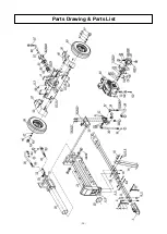
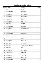
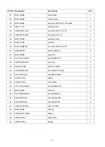
Page 20: ...20 Parts Drawing Parts List...


