background image

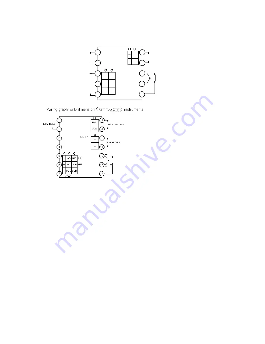
Wiring graph for D2 dimension

48X48mm

instruments


1


2


3


4


5


6


7


9


10

8


COM

N/O

+

100-240VAC~


AU1

AUX 

AU2

COM

COM

N/O

N/C 

N/O

N/O 

+

Main Output 

OUTP

Alarm 

Output


Summary of Contents for AI-208

Page 1: ...ARTIFICIAL INTELLIGENCE TEMPERATURE CONTROLLER AI 208 V7 6 User Manual ...

Page 2: ...e Suit for 0 999 application Maximum support two alarms contact output Universal voltage input 100 240VAC ISO9001 certification and CE certified achieving word class level of quality anti interference ability and safety 2 Part 2 Front panel dimension Size Front Panel width height Cut Out width height Depth Behind Mounting Surface A 96 96mm 92 92mm 100mm B 160 80mm 76 152mm 100mm D 72 72mm 68 68mm ...

Page 3: ...upport AL1 and AL2 alarm output G SSR voltage output module 30mA 5VDC II TECHNICAL SPECIFICATION 1 Input type Thermocouple K E J N Resistance temperature Detector Pt100 2 Instrument Input range K E J N 0 999 Pt100 0 800 3 Measurement accuracy 0 3 FS 1 4 Temperature display resolution 1 5 Control mode On off control mode AI artificial intelligence control including fuzzy logic PID control and advan...

Page 4: ...igence control and auto tuning When AI artificial intelligence control method is chosen CrL AI the PID parameters can be obtained by running auto tuning In basal display status press for 2 seconds the At parameter will appear Press to change the value of At from oFF to on then press to active the auto tuning process During auto tuning the instrument executes on off control After 2 3 times of on of...

Page 5: ...L Control mode z onF On off control When PV SV Output stop When PV SV CHY start output z AI AI PID control high precision and no overshoot P Proportion band Proportion band in PID with unit 1 999 I Time of Integral Time of Integral in PID No integral effect when I 0 0 999 Sec d Time of Derivative Time of Derivative in PID No derivative effect when d 0 0 999 Sec Ctl Control period Small value can i...

Page 6: ...d FIL s can be set to 0 or 1 to shorten the response time 0 40 Fru Selection of power frequency and temperature scale 50C 50Hz 50F 50Hz 60C 60Hz 60F 60Hz SPH Upper limit of SV Maximum value that SV allowed to be When SPH 400 the SV range will 0 400 0 999 VI INSTRUMENT INSTALLATION AND WIRING Wiring graph for instruments with dimension A B E or F Note The graph suits for upright instruments with di...

Page 7: ...Wiring graph for D2 dimension 48X48mm instruments 1 2 3 4 5 6 7 9 10 8 COM N O 100 240VAC AU1 AUX AU2 COM COM N O N C N O N O Main Output OUTP Alarm Output ...

Reviews: