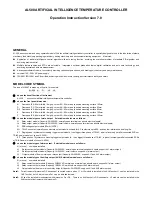
3
PARAMETER AND SETTING
●
Press
and hold for 2 seconds to access
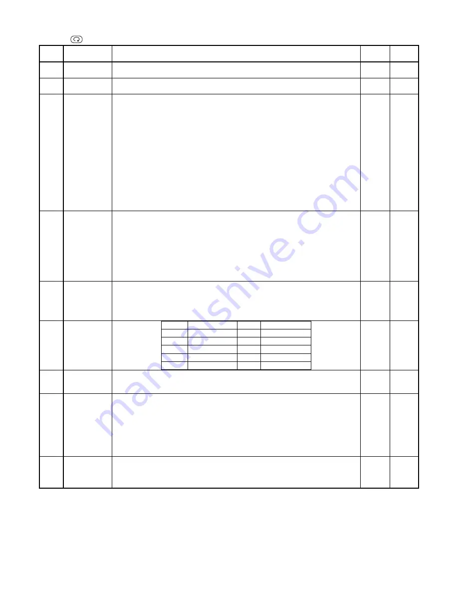
Code Name
Description
Setting
Range
Default
HIAL
High limit alarm
Alarm on when PV (Process Value) >HIAL; alarm off when PV<HIAL-dF
Setting HIAL=9999 can disable high limit alarm.
-1999
~
3000
℃
9999
HdAL
Deviation high
alarm
Alarm on when PV-SV>HdAL; alarm off when PV-SV<HdAL-dF
Setting dHAL=999.9
℃
can disable deviation high alarm.
0
~
999.9
℃
999.9
dF
deadband
(hysteresis)
Avoid frequent on-off action of alarm or control output because of the fluctuation of PV.
“dF” can affect alarm. For example, provided upper alarm parameter "HIAL" is set as 800
℃
, dF
parameter is set as 2.0
℃
, then:
Instrument is in normal status at the beginning, when process value is greater than 800
℃
(HIAL), the upper limit alarm can be triggered.
Instrument is in upper alarm status at the beginning, when process value is less than 798
℃
(HIAL-dF), then alarm can be cleared.
“dF” also affect on-off control and auto tuning. For example, provided SV is set as 700
℃
, dF
parameter is set to 2
℃
, control is reverse action (heat control).
when process value is greater than 700
℃
(SV), then output turn off.
when process value is less than 698
℃
(SV-dF), output trun on again to start heating.
As for on-off control, the larger for dF parameter value, the longer for CtI (output period time) and
the worse for control accuracy. Conversely, the smaller for dF parameter, the shorter for CtI, then
the better for control accuracy, but error action will occur easily due to input fluctuation and
shorten the service life of mechanical contactors of relay.
0
~
200.0
℃
20
℃
CtrL
Control mode
0: on-off control. For situation not requiring high precision;
1: AI control. Allowed to active auto-tuning in basic display status.
2: Run auto-tuning. After auto-tuning finishes, it will automatically change to 3 or 4.
3: AI control, this configuration is automatically set after auto tuning is done. At this setting,
starting auto tuning at basic display status is inhibited and it can prevent from running auto tuning
by mistake.
4: Similar to CtrL=3, but parameter P is defined as 10 times as its original value, suitable for
rapidly changed temperature (changes by more than 100
℃
/second). Auto tuning function can
automatically set CtrL to 3 or 4.
0
~
4 1
CtI
Control period
Small value can improve control accuracy.
For SSR or TRIAC output, generally 0.5 to 3 seconds.
For Relay output, generally 15 to 45 seconds, because small value will cause the frequent On-Off
of mechanical switch and shorten its service life. CtI is recommended to be 1/4 – 1/10 of
derivative time. (It should be integer times of 0.5 second.)
0.5
~
125
seconds
2
seconds
Sn
Input
specification
Sn
Input spec.
Sn
Input spec.
0
K
1
S
2
R
3
Spare
4
E
5
J
6
Spare
7
N
8-20
Spare
21
Pt100
0
~
21 0
Sc
Input offset
Sc is used to shift input to compensate the error caused by transducer, input signal, or auto cold
junction compensation of thermocouple.
PV_after_compensation=PV_before_compen Scb
-199.9
~
+400.0
℃
0.0
dL
input digital filter
If measurement input fluctuates due to noise, then digital filter can be used to smooth the input.
Parameter “dL” may be configured in the range of 0 to 20, among which, 0 means no filter, 1
means intermediate-value filter, and 2—20 means that intermediate-value filter and second order
integral filter working simultaneously.
The bigger dL, the more stable the measurement input but the slower the response. Generally if
great interference exist, then you can increase parameter “dL” gradually to make momentary
fluctuation of measurement input less than 2 to 5 values. If the instrument is being tested at
laboratory, then parameter “dL” should be set to 0 or 1 to improve response speed.
0
~
40 1
Loc
Parameter Lock
Loc=0,
allowed to modify parameters and setpoint.
Loc=1,
allowed to view parameters, but can’t modify them. And allowed to set setpoint.
Loc=2,
allowed to view parameters, but not allowed to modify parameters or setpoint (except
parameter Loc itself).
0
~
9999
111
Note :
Generally, before shipping, the HIAL (high limit alarm) is set to output to AL1, and dHAL (deviation high limt alarm) outputs to AU1 (ALP=5533).
However, D2 dimension instruments only have AUX slot. If single relay output module L1 or L2 is installed, HIAL and dHAL should be set to share an
alarm output AU1 (ALP=5555); if dual relay output module L5 is installed, HIAL and dHAL should separately output to AU2 and AU1 (ALP-5566). Expert
users can change alarm outputs, add low limit or deviation low limit alarm, or hide some parameters by setting internal ALP and EP parameters. You can
call your provider for details.


