User Manual
User Manual
User Manual
User Manual
220V
24V
Sig On
Sig OFF
T
DELAY
OPEN
DELAY
OPEN
T1
MODE B
MODE A
1. Uses
2. Power Supply
TW 600
TW 600
TW 600
TW 600
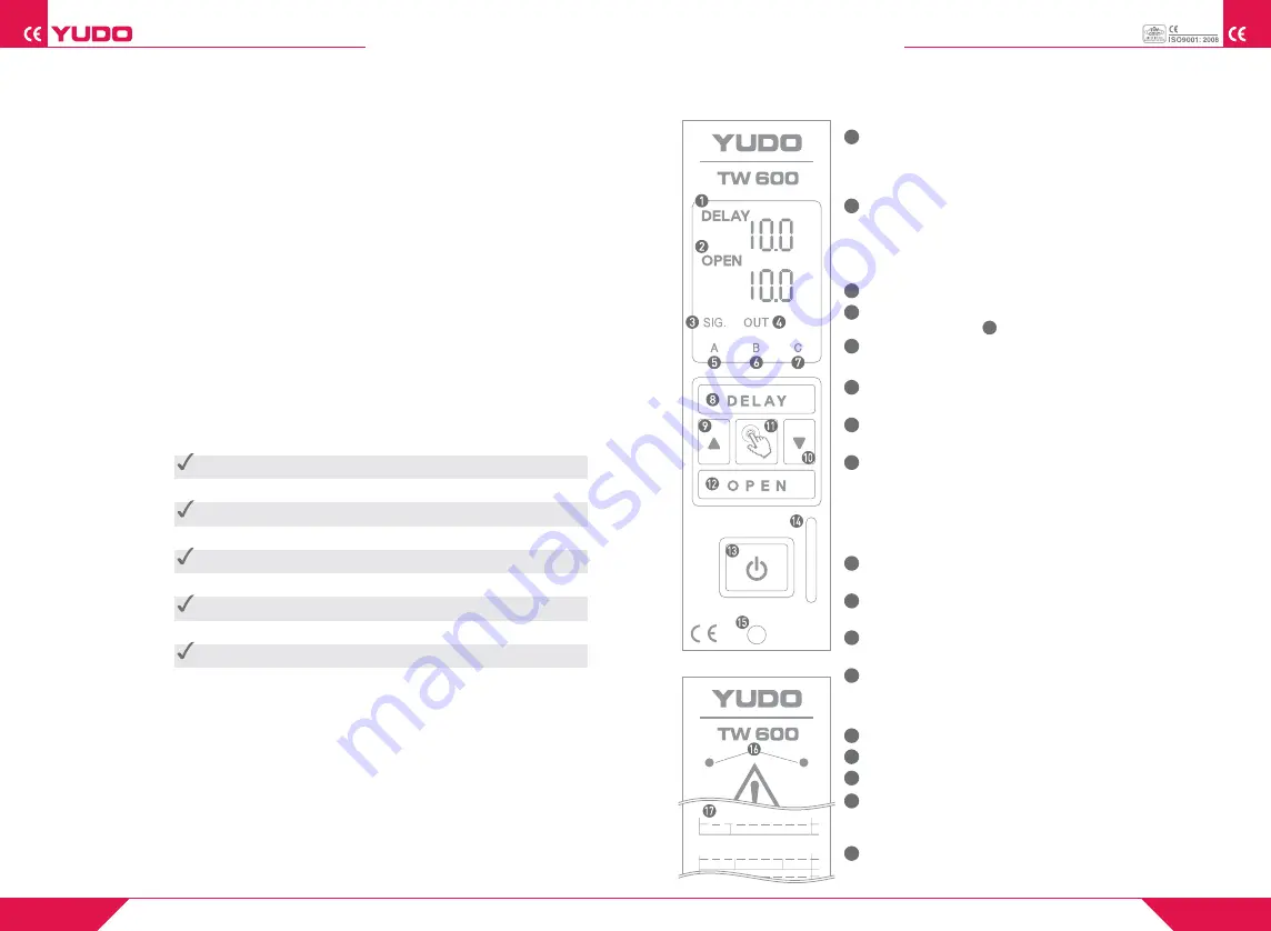
3. TW 600 Parts name
Blank panel
YUDO Sequence Injection System is to provide a means of controlling the mould
filling sequence when Valve Gate Hot Runner System. The sequence
injection Timer enables the Valve Gates of a Hot-Runner System to
be individually controlled to provide the following benefits.
1) Removal or Positioning of Weld Line
Quality of the Molded part can be improved by removing or
re-positioning of weld lines on visual surfaces, or sections where a
weld line would cause a weakness.
2) Regulation of the Injection Quantity by Gate operation
Injection balance can be adjusted in Family mould application.
3) Improvement on Flash and short-shot
By Gate open control in an orderly manner, it can eliminate Flash
and short-shot problem.
1
2
3
4
5
6
7
8
9
10
11
12
13
14
15
16
17
SEQUENCE INJECTION TIMER
SEQUENCE INJECTION TIMER
3
4
Main Power Supply (Timer Case) AC(85~264VAC),50/60 Hz
Injection Signal Input Power DC 24V, AC 110V, AC 220V
Free Voltage
Solenoid Valve output voltage DC 24V, AC110V, AC220V
*AC Solenoid Valve output must be same with AC input power .
Operating temperature 0℃
~ 50
℃
PCB Structure
①
Power board Power PCB
②
Relay board Relay (Solenoid Valve on/off)
③
CPU board MPU, out signal Input/Output,
Display, Switch Signal input
④
Front board Solenoid Valve output display
(24V or 220V)
⑤
Mother board DC Main Power distribution and
Connector
DELAY The time until gate is started to be opened
after receiving injection signal.
Mode A, Mode B, Mode C operates in the
same way.
( Basic setting value : 3 sec. )
OPEN The time when gate is being opened.
Counting continues in mode A until injection
signal ends. Gate opens only during setting
time in Mode B and Mode C.
( Basic setting value : 3 sec. )
SIGNAL LED Lamp is turned on, as injection signal is input.
OUT LED Lamp is turned on, as Gate is open.
In manual mode, it operates in the same way.
MODE A LED Lamp is turned on when it is set as A type
( Refer to 5-page, Mode setting )
MODE B LED Lamp is turned on when it is set as B type
( Refer to 5-page, Mode setting )
MODE C LED Lamp is turned on when it is set as B type
( Refer to 5-page, Mode setting )
DELAY SET Key A key to set gate opening time after injection signal.
("SAVE" is displayed 3 seconds after setting, and
then setting value is saved. If signal is turned on
before "save" display, it operates with the
changed value. If input power is turned off and
then turned on, setting value is not saved).
UP Key A key to set up tim by pressing DEL or
OPEN SET Key simultaneously .
DOWN Key A key to turn down time setting by pressing
DEL or OPEN SET key simultaneously.
Manual Output Key A Key to open Gate manually.
It operates only when the key is being pressed.
OPEN SET Key A key to set the time when gate is being opened.
This is used by pressing key or key simultaneously.
( Save function is the same as DEL SET key )
Main power switch
Unit take-out Bar
Unit fixing Bolt
Solenoid Valve output power supply display
The Voltage must be same as Solenoid Valve
input Voltage in mold.
(AC 220V / DC 24V)
MODE operation Specification
11


