24
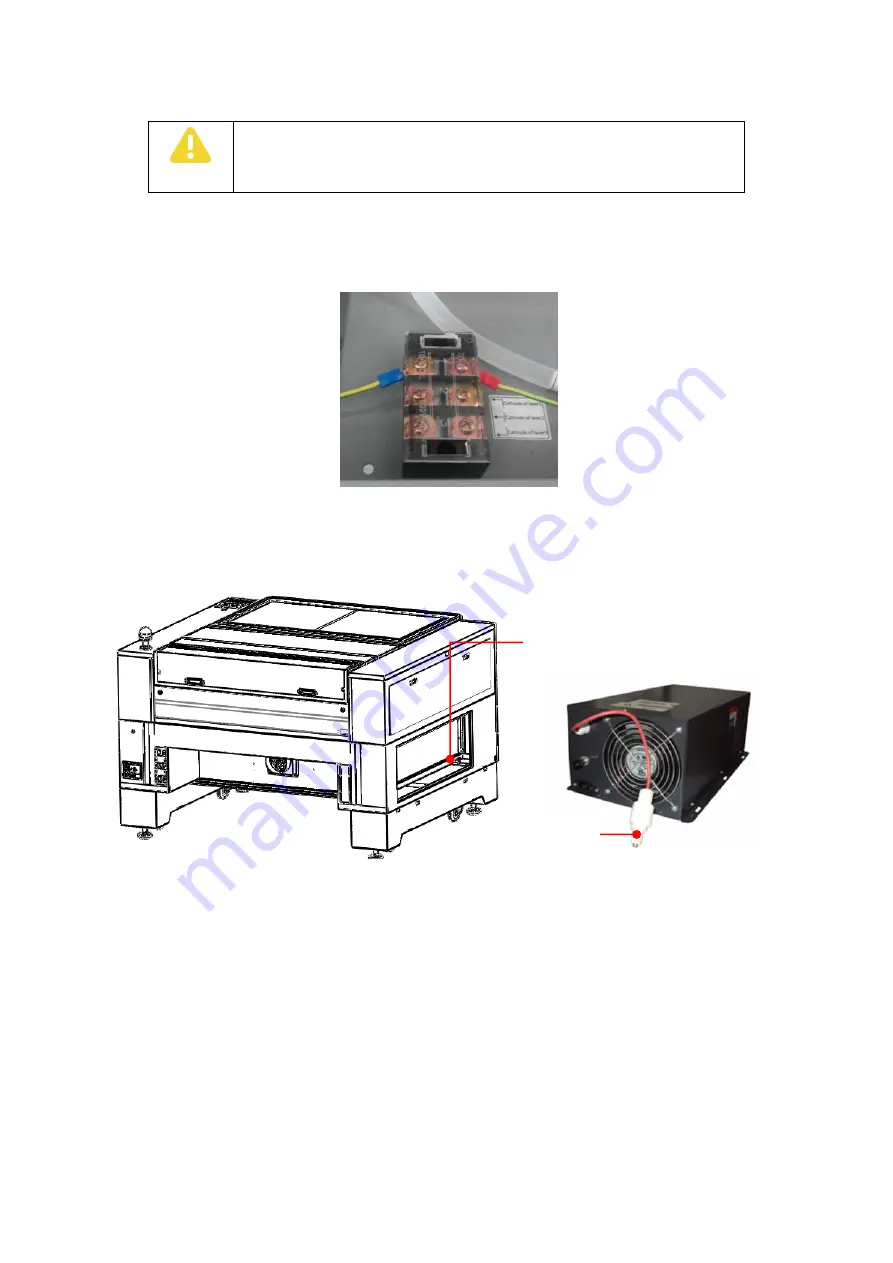
Then, connect the negative line of the laser tube to the wiring terminal in the lower left corner of the
optical pipe cover according to the identification, and finally connect the high voltage end of the laser
tube to the laser power through threading hole in the rack, as shown below:
Figure 3-9
Laser Negative Terminal
3.1.4.3
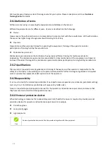
Laser power supply installation
Figure 3-10
Laser Power Installation Position Diagram
Note
:
Under normal condition, before the factory, the laser power supply has been installed.
The installation of the positive high voltage connector of the laser power is shown below:
Attention
All water pipes must be connected firmly to prevent leakage.
The hose must be straightened to ensure smooth water flow.
Laser power
installation location
High voltage
connector


