36
3.3.2.1
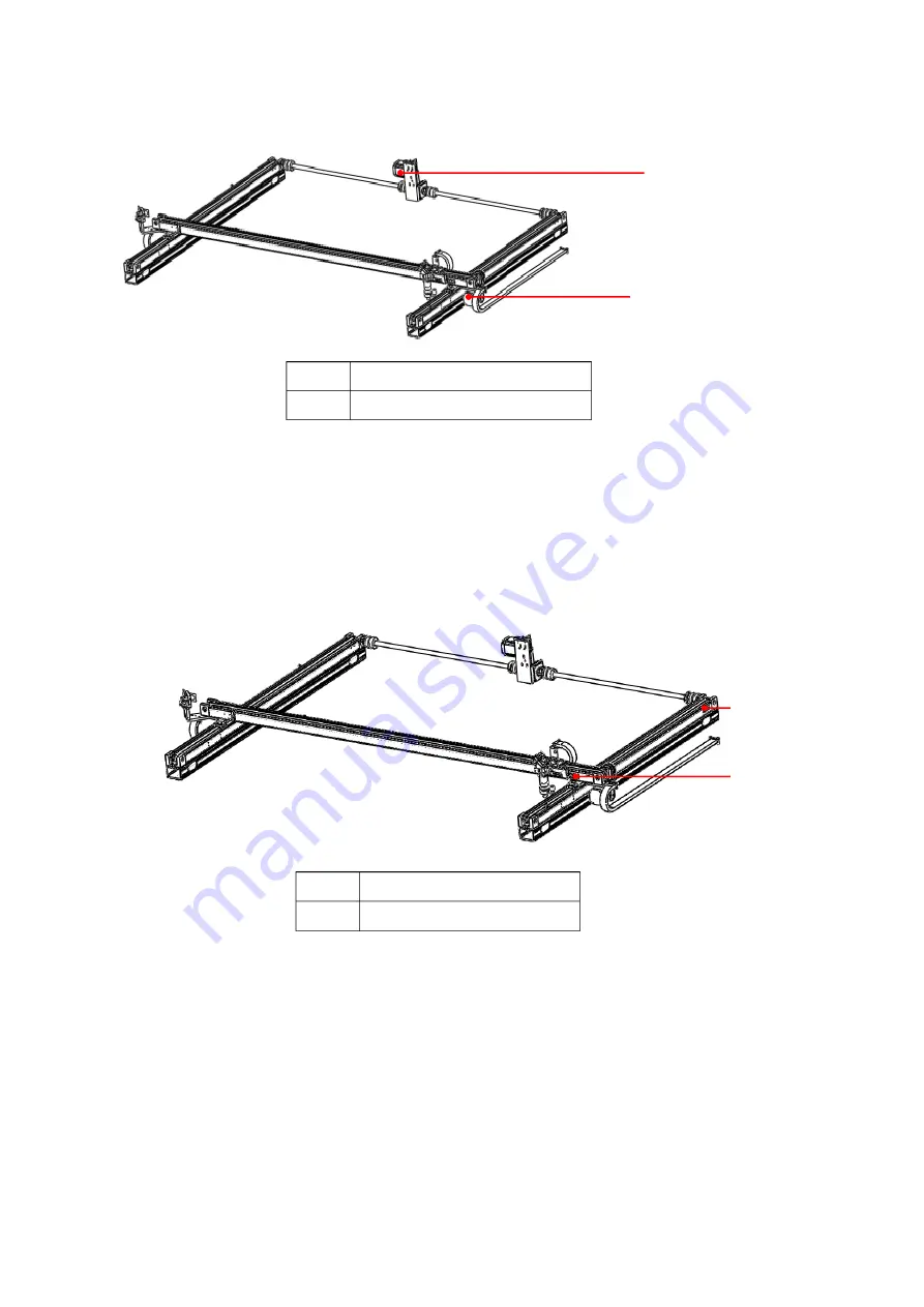
Motor shaft movement
Figure 3-24
Motor Position Diagram
After powering on, start the computer and run SmartCarve4.3. If the software is set to reset automatically,
the resetting starts. In standby mode, press the four direction keys on the control panel to control the movement
of the cutting head. If the movement in the four directions is normal, the motor movement in X -axis and Y -axis is
normal. If you find any problem in motor shaft movement, please contact our customer service personnel.
3.3.2.2
Stroke, limit and reset
Figure 3-25
Limit Switch Position Diagram
Different models of machine are with different working breadth, and setting stroke of each shaft of the
machine will play the function of breadth protection (equals to software limit).
The travel parameters for each axis have been set up. Improper travel settings may cause the equipment
unable to work in full breadth or cutting head over-limit and collision. For example, the effective processing
breadth of CMA1309-B-A is theoretically 1300mm X 900mm, but it should be set in the controller according to
actual cutting breadth in practice.
①
②
①
Y-axis motor
②
X-axis motor
①
②
①
Y
Limit switch
②
X
Limit switch


