CLM920_TE5 LTE Module Hardware Manual
20
YUGA Information Technology Co.,Ltd
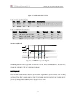
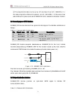
Figure 3- 9 Reset Reference Circuit
Table 3- 5 Reset Pin Definition
Pin Name
I/O
High value Description
22
RESET
DI
1.8V
Module reset control pin, active low
28
PWRKEY NC
NC
NC
Table 3- 6 RESET Pin Definitions
Symbol
Description
Min
Typical
Max
Unit
Treset
Low level pulse width
150
200
450
ms
VIH
RESET high level input
1.17
1.8
2.1
V
VIL
RESET low level input
-0.3
0
0.8
V
RESET sequence
:
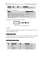
Figure 3- 10 RESET sequence diagram
CLM920_TE5 module support AT command to reset, that is AT+CFUN=1,1. Details can
check the CLM920_TE5 AT command manual.
3.4.1 Power off
The module will shutdown without “power down registration” process when turn it off by
cutting off the VBAT power supply. Only if the module is abnormal and can’t restart by AT,
you may cutting off the VBAT power supply can be used.
VBAT
PWRKEY
VDD_EXT
RESET
PowerOn sequence
On
Reset
Restart
>=150mS
<=450mS
Module Status


