background image

                                                                                                                                  CLM920_TE5  LTE  Module  Hardware  Manual


YUGA Information Technology Co.,Ltd 

2.2 Key Features


Table 2- 1 Operating frequency band 

Network 

Band 

Product Series


CLM920_TD5             CLM920_TE5 

CLM920_NC5 

GSM 

GSM850 


GSM900 


GSM1800 


GSM1900 


LTE(FDD) 

LTE FDD B1 


LTE FDD B2 


LTE FDD B3 


LTE FDD B4 


LTE FDD B5 


LTE FDD B7 


LTE FDD B8 


LTE FDD B17 


LTE FDD B20 


LTE FDD B28 


LTE(TDD) 

LTE TDD B38 


LTE TDD B39 


LTE TDD B40 


LTE TDD B41 


TD-SCDMA 

TD-SCDMA B34 


TD-SCDMA B39 


WCDMA 

BAND 1 


BAND 2 


BAND 3 


BAND 5 


BAND 8 


CDMA1x/EVDO 

BC0 

(optional) 


GNSS 

GLONASS 


GPS 


BeiDou/Compass 


Category 1 


GNSS function is optional. 

The module supports Cat4 as default. In case of Cat1 module, label is different. 

Cat1 doesn’t support diversity antenna. 

Summary of Contents for CLM920_TE5

Page 1: ...TE Module Hardware Manual Version 1 1 Address Office 603 Building E No 666 Shengxia Road Shanghai China HomePage http www yuge info com Mail Support yuge info com Tel 021 50177336 YUGA Information Technology Co Ltd ...

Page 2: ...2 Revision Date Description Author V1 0 20170710 Initial David V1 1 20170825 Cheung ...

Page 3: ...3 3 4 Power on sequence 19 3 4 Reset control 19 3 4 1 Power off 20 3 5 USB interface 21 3 6 UART interface 22 3 7 USIM interface 23 3 7 1 USIM card reference circuit 23 3 7 2 UIM_DET Hot Plug Reference Design 24 3 8 General purpose GPIO interface 25 3 9 Network Indication Interface 25 3 10 Analog voice interface 26 3 10 1 Analog Voice Reference Design 26 3 10 2 Analog Voice Reference Design 27 3 1...

Page 4: ... 4 6 Power consumption characteristics 36 5 Interface electrical characteristics 37 5 1 Operating Storage Temperature 37 5 2 Module IO electrical characteristics 37 5 3 Power supply characteristics 38 5 4 Electrostatic characteristics 38 6 Structural and mechanical properties 38 6 1 Appearance 38 6 2 Mini PCI Express connector 39 6 3 Module fixing method 39 ...

Page 5: ...3 10 RESET sequence diagram 20 Figure 3 11 USB design circuit diagram 21 Figure 3 12 UART serial port design 22 Figure 3 13 Level conversion circuit 23 Figure 3 14 USIM design circuit 23 Figure 3 15 Hot plugging of the USIM card 24 Figure 3 16 WAKEUP_OUT signal wave 25 Figure 3 17 network indicator circuit diagram 26 Figure 3 18 Analog voice reference circuit 27 Figure 3 19 External audio codec re...

Page 6: ... 13 Network indicator status 26 Table 3 14 Analog voice pin definitions 26 Table 3 15 PCM Pin Definition 28 Table 3 16 PCM Parameter 28 Table 3 17 RF Connector Parameters 30 Table 4 1 RF Frequency Table 32 Table 4 2 Test Instruments 32 Table 4 3 2G 3G RF specifications 33 Table 4 4 4G RF sensitivity index 33 Table 4 5 4G RF transmission power 34 Table 4 6 Main Antenna specifications 35 Table 4 7 G...

Page 7: ...ct Overview 2 1 General Description CLM920_TE5 module provides data connectivity on FDD TDD TD SCDMA UMTS EVDO CDMA EDGE GSM networks and integrated GPS service with PCI Express Mini Card 1 2 standard interface The module bases on Qualcomm s MDM9x07 supports Cat4 which upload download speed can reach 50Mbps 150Mbps fully supports VOLTE and SRLTE and supports embedded operating system such as Windo...

Page 8: ...TE FDD B2 LTE FDD B3 LTE FDD B4 LTE FDD B5 LTE FDD B7 LTE FDD B8 LTE FDD B17 LTE FDD B20 LTE FDD B28 LTE TDD LTE TDD B38 LTE TDD B39 LTE TDD B40 LTE TDD B41 TD SCDMA TD SCDMA B34 TD SCDMA B39 WCDMA BAND 1 BAND 2 BAND 3 BAND 5 BAND 8 CDMA1x EVDO BC0 optional GNSS GLONASS GPS BeiDou Compass Category 1 GNSS function is optional The module supports Cat4 as default In case of Cat1 module label is diffe...

Page 9: ...ion Interface Standard SIM interface support 3 0V 1 8V support hot plug USB2 0 High Speed Hardware reset interface UART serial interface PCM Analog voice interface Power interface Network status indication interface GPIO interface Antenna connector Main Antenna Connector MM4829 2702RA4 Diversity Antenna connectorMM4829 2702RA4 GPS Antenna connector MM4829 2702RA4 Transmitting Power LTE Class 3 23d...

Page 10: ...0M BW cat1 Satellite positioning GPS BEIDOU GLONASS Protocol NMEA Diversity antenna Supports LTE diversity antenna AT instruction Supports standard AT command set Hayes 3GPP TS 27 007 和 27 005 SMS Text and PDU mode Point to point MO and MT SMS storage USIM card ME by default Virtual network card Support USB virtual network card Temperature Range Normal operation 35 C to 75 C Restricted operation 4...

Page 11: ... 3 Application Interface 3 1 General Description This chapter mainly describes the application interface of this module Contains the following sections 52 pin Interface definition Power interface USB interface USIM interface UART interface PMU VBAT VDD_EXT MCP RF FEM Qualcomm Chip MMPA USIM UART PCM USB GPIO ADC Analog voice ONOFF RESET MOUDLE interface GNSS RF BB RF Transceiver 19 2MHZ Main Anten...

Page 12: ...al 12 YUGA Information Technology Co Ltd WWAN control interface PCM Analog voice interface RF antenna interface 3 2 Module Interface 3 2 1 52 pin The CLM920_TE5 module use 52 pin as an external interface Figure 3 1 TOP and BOTTOM of Pins ...

Page 13: ...escription IO Bidirectional input and output PI Power input PO Power output AI Analog input AO Analog output DI Digital input DO Digital output Table 3 2 Interface definitions Pin Standard Pin Definitions Module pin definition IO Functional description Remarks 1 WAKE MIC AI Audio input 2 3 3Vaux VBAT PI Power input 3 COEX1 MIC AI Audio Input 4 GND GND Ground 5 COEX2 SPK REC AO Audio output set hea...

Page 14: ...gnal 15 GND GND Ground 16 UIM_VPP NC 17 RESERVED VDD_EXT PO 1 8V output 18 GND GND Ground 19 RESERVED WAKEUP_IN DI HOST wake up module 1 8V Active low 20 W_DISABLE W_DISABLE DI turn off RF Active low 21 GND GND Ground 22 PERST RESET DI Reset control Active low 23 PERn0 UART_CTS DI Serial Port Send Clear 24 3 3Vaux VBAT PI power input 25 PERp0 UART_RTS DO Serial request to send 26 GND GND Ground 27...

Page 15: ...rved 45 RESERVED PCM_CLK DO PCM clock pulse 46 LED_WPAN NC Reserved 47 RESERVED PCM_DOUT DO PCM data output 48 1 5V NC 49 RESERVED PCM_DIN DI PCM data input 50 GND GND Ground 51 RESERVED PCM_SYNC DO PCM frame sync 52 3 3Vaux VBAT PI Power input The module s general IO port level is 1 8V except SIM the SIM card port level supports 1 8V and 3 0V Recommend do not use the module s pins which are defin...

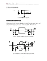
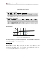
Page 16: ...er supply pin with 14 pin GND VBAT power supply range of 3 3 4 2V the recommended power supply is 3 7V 2A The module s peak current will reach 2 5A when transmit data or call under HSPA UTMS GSM which resulting in a large ripple on the power If instant voltage drop makes the VBAT power too low or the current supply insufficient the module will power off or restart To ensure that the module works p...

Page 17: ... enough current Refer to the following design Figure 3 5 Reference Design of LDO linear power supply Figure 3 6 Reference Design of DC switching power supply VIN EN GND OUT ADJ MIC29302WU 4 5 3 1 2 100uF 0 1uF 1uF 220uF 47K 100K 0 1uF VBAT G EN DC_5V 470uF VBAT 470uF 1uF 100nF F 10pF 33pF 2 1 1 10 7 8 9 3 12 4 5 6 1 3 1 220uF 2 2uF 100nF DC_EN VIN 20K 10nF 620R 10K SK34 100pF 220uF 1 1uF 0 1uF VBA...

Page 18: ...nF near to the VBAT pin The minimum working voltage of the module is 3 3V Due to the peak current will reach 2 5A while transmit data or call under GSM making a large ripple on the power the supply voltage can t lower than 3 3V 3 3 3 VDD_EXT 1V8 output The pin 17th will output 1 8V after CLM920_TE5 module boots up successfully Its maximum current load is 50mA Using this PIN you can determine wheth...

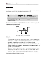
Page 19: ...e Judge by the USB 20 ms Ton uart Boot time Judge by the UART 20 ms VIH PWRKEY high level input 0 6 0 8 1 8 V VIL PWRKEY low level input 0 3 0 0 5 V 3 4 Reset control CLM920_TE5 module s reset pin is 22nd Pull this pin low 150 450ms to reset the module Recommended that the external pull up resistor 10K to VDD_EXT This pin is sensitive to interference need to protection circuit Ton Ton status Ton u...

Page 20: ...RESET high level input 1 17 1 8 2 1 V VIL RESET low level input 0 3 0 0 8 V RESET sequence Figure 3 10 RESET sequence diagram CLM920_TE5 module support AT command to reset that is AT CFUN 1 1 Details can check the CLM920_TE5 AT command manual 3 4 1 Power off The module will shutdown without power down registration process when turn it off by cutting off the VBAT power supply Only if the module is ...

Page 21: ...SB design circuit diagram USB interface supports High speed 480Mbps and Full speed 12Mbps mode USB designed to strictly follow the USB2 0 protocol requirements wiring attention to the data line protection differential traces the control impedance of 90Ω In order to improve the anti static performance it is recommended that ESD protection devices should be added to the data lines the equivalent cap...

Page 22: ... 115200bps UART interface is defined as follows Table 3 8 UART signal definitions Pin Signal name I O Description 11 UART_RX DI UART receive data 13 UART_TX DO UART transmit data 23 UART_CTS DI user allows the module to transmit 25 UART_RTS DO Module requests the user to send If need to use the serial port please refer to the following serial port design Figure 3 12 UART serial port design The mod...

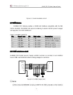
Page 23: ...IM_DET DI 1 8V SIM hot plug detection 8 UIM_PWR PO 1 8V 2 85V SIM card power supply 10 UIM_DATA IO 1 8V 2 85V SIM data signal 12 UIM_CLK DO 1 8V 2 85V SIM clock signal 14 UIM_RESET DO 1 8V 2 85V SIM reset signal 3 7 1 USIM card reference circuit CLM920_TE5 module need to design a USIM card slot on customer s own interface board USIM card interface reference design diagram is as follow Figure 3 14 ...

Page 24: ...us of the SIM card through this PIN when hot plugging The 22R resistors should be added in series between the module and USIM card to protect USIM card The ground of USIM slot and module have to maintain good connectivity 3 7 2 UIM_DET Hot Plug Reference Design CLM920_TE5 module supports SIM hot plugging UIM_DET pin as an input detective pin to determine whether the SIM card is inserted or not UIM...

Page 25: ...dule sleep control 20 W_DISABLE DI 1 8V Disable RF 32 WAKEUP_OUT DO The module wakes up the host open drain CLM920_TE5 module supports sleep wake up WAKEUP_IN for the host controls module s sleep wake up WAKEUP_OUT for the module to wake up the host Use the command AT RPTFLAG 0 to enable the wake up function when power on Figure 3 16 WAKEUP_OUT signal wave The host can wake up module by WAKEUP_IN ...

Page 26: ...rence design is as follow Figure 3 17 network indicator circuit diagram LED light s brightness can be adjusted by limiting the value of resistance the maximum current can be adjusted to 40mA 3 10 Analog voice interface CLM920_TE5 module provides a set of analog voice interfaces including one differential input signal MIC MIC and one differential output signal SPK SPK 3 10 1 Analog Voice Reference ...

Page 27: ...ovided microphone bias voltage for the operation from internal and external bias circuit is not needed Mic usually use the electric microphone SPK SPK channel usually used for handset or headset When using external power amplifier switch the module to headset output by AT CSDVC 4 then connect PIN1 PIN3 PIN5 PIN7 Module FB2 FB1 FB4 FB3 33pF 10pF 33pF 10pF 33pF F 10pF 33pF 10pF MIC SPK Close to SPK ...

Page 28: ...et output by AT CSDVC 4 headset output by AT CSDVC 2 Adjust the handset output volume gain by AT COUTGAIN and set the Mic gain by AT CMICGAIN More details refer to the AT manual 3 11 PCM audio interface CLM920_TE5 module provides one PCM audio interface which supports 8 bit A law and μ law 16 bit linear data formats PCM_SYNC is 8kHZ PCM_CLK is 2048kHZ Table 3 15 PCM Pin Definition Pin Signal Name ...

Page 29: ... which used to help the signal drop by high speed moving or multipath fading 3 12 1 RF Connector Location Figure 3 21 RF connector location map 3 12 2 RF Connector The connection mode of using RF Connector is recommended The antenna connector must use a 50Ω characteristic impedance coaxial connector and choose the RF cables which insertion loss as low as possible It is recommended to use Murata s ...

Page 30: ... 3 23 Recommended Coaxial RF Cable Dimensions The connection to the antenna must be a 50Ω characteristic impedance The antenna matching circuit parameters can optimized by users based on the user s circuit board Resistor R1 R2 R3 R4 is 0Ω by default and C1 C2 C3 C4 is empty by default To prevent electrostatic damage to the module s components it is suggested that choosing a low capacitance ESD dev...

Page 31: ...d without diversity antenna 4 Overall Technical Indicators 4 1 Overview of this chapter CLM920_TE5 module radio contains the following sections Operating frequency Conducted RF measurements Conducted receiver sensitivity and transmit power Operating current Antenna requirements GND DIV_ANT MAIN_ANT Matching circuit C2 C1 D1 D2 C4 C3 R3 R4 R1 R2 GNSS Antenna ...

Page 32: ...803 MHz FDD LTE B38 2570MHz 2620MHz 2570MHz 2620MHz TDD LTE B39 1880MHz 1920MHz 1880MHz 1920MHz TDD LTE B40 2300MHz 2400MHz 2300MHz 2400MHz TDD LTE B41 2496MHz 2690MHz 2496MHz 2690MHz TDD GSM850 824MHz 849MHz 869MHz 894MHz GSM GSM900 880MHz 915MHz 925MHz 960MHz GSM DCS1800 1710MHz 1785MHz 1805MHz 1880MHz GSM PCS1900 1850MHz 1910MHz 1930MHz 1990MHz GSM UMTS B1 1920MHz 1980MHz 2110MHz 2170MHz WCDMA ...

Page 33: ...MHz 869MHz 894MHz 33 2dBm 109dBm GSM 900 880MHz 915MHz 925MHz 960MHz 33 2dBm 109dBm DCS 1800 1710MHz 1785MHz 1805MHz 1880MHz 30 2dBm 109dBm PCS 1900 1850MHz 1910MHz 1930MHz 1990MHz 30 2dBm 109dBm WCDMA B1 1920MHz 1980MHz 2110MHz 2170MHz 23 2 2dBm 109dBm WCDMA B2 1850MHz 1910MHz 1930MHz 1990MHz 23 2 2dBm 109dBm WCDMA B5 824MHz 849MHz 869MHz 894MHz 23 2 2dBm 109dBm WCDMA B8 880MHz 915MHz 925MHz 960M...

Page 34: ...E B38 TDD QPSK 通过 95 96 3 10 MHz 98 97 LTE B39 TDD QPSK 通过 95 96 3 10 MHz 99 98 LTE B40 TDD QPSK 通过 95 96 3 10 MHz 99 98 LTE B41 TDD QPSK 通过 95 96 3 10 MHz 98 97 Table 4 5 4G RF transmission power Directory 3GPP protocol requirements dBm Min Typical Max LTE B1 21 to 25 22 23 24 LTE B2 21 to 25 22 23 24 LTE B3 21 to 25 22 23 24 LTE B4 21 to 25 22 23 24 LTE B5 21 to 25 22 23 24 LTE B7 21 to 25 22 23...

Page 35: ...DD 2 5 1 4dbi 40 19 94 B17 FDD 2 5 1 4dbi 40 19 94 B20 FDD 2 5 1 4dbi 40 19 94 B28 FDD 2 5 1 4dbi 40 19 94 B38 TDD 2 5 1 4dbi 40 19 93 B39 TDD 2 5 1 4dbi 40 19 93 B40 TDD 2 5 1 4dbi 40 19 93 B41 TDD 2 5 1 4dbi 40 19 93 WCDMA B1 2 5 1 4dbi 40 19 106 WCDMA B2 2 5 1 4dbi 40 19 106 WCDMA B5 2 5 1 4dbi 40 19 106 WCDMA B8 2 5 1 4dbi 40 19 106 EVDOrA 2 5 1 4dbi 40 19 106 B34 TDS 2 5 1 4dbi 40 19 106 B39 ...

Page 36: ...UP 1DL 5 315 GPRS1800 1UP 1DL 0 200 GPRS1900 1UP 1DL 0 192 EDGE850 1UP 1DL 8 220 EDGE900 1UP 1DL 8 225 EDGE1800 1UP 1DL 2 175 EDGE1900 1UP 1DL 2 170 Table 4 9 WCDMA power consumption Table 4 10 LTE power consumption Frequency band Power dBm Current consumption mA B1 21 5 562 B2 23 6 608 B3 21 8 590 B4 23 3 618 Frequency band Power dBm Current consumption mA WCDMA B1 23 2 556 WCDMA B1 1 165 WCDMA B...

Page 37: ...nd Power dbm Current consumption mA BC0 24 621 5 Interface electrical characteristics 5 1 Operating Storage Temperature Table 5 1 4G module operation and storage temperature Parameter Min Max Normal working temperature 35 C 75 C Limit working temperature 40 C 85 C Storage temperature 45 C 90 C 5 2 Module IO electrical characteristics CLM920_TE5 module s IO level is as follows The UIM_PWR is 1 8V f...

Page 38: ...meter Min Typical Max VBAT 3 3V 3 7V 4 2V UIM_PWR 1 7V 2 75V 1 8V 2 85V 1 9V 2 95V The power on time of any Host interface must not be earlier than the power on time of the module Otherwise the module may be abnormal or damaged 5 4 Electrostatic characteristics CLM920_TE5 module requires ESD protection to ensure product quality in using Table 5 4 CLM920_TE5 ESD Characteristics Test port Contact di...

Page 39: ... PCI Express connector CLM920_TE5 module interface meets the PCI Express Mini Card 1 2 interface standard PCI Express Mini Card connectors conforming to this standard can be used such as Molex 679100002 Figure 6 2 Connector dimensions 6 3 Module fixing methodd CLM920_TE5 module is fixed with two grounding screw holes ...

Reviews: