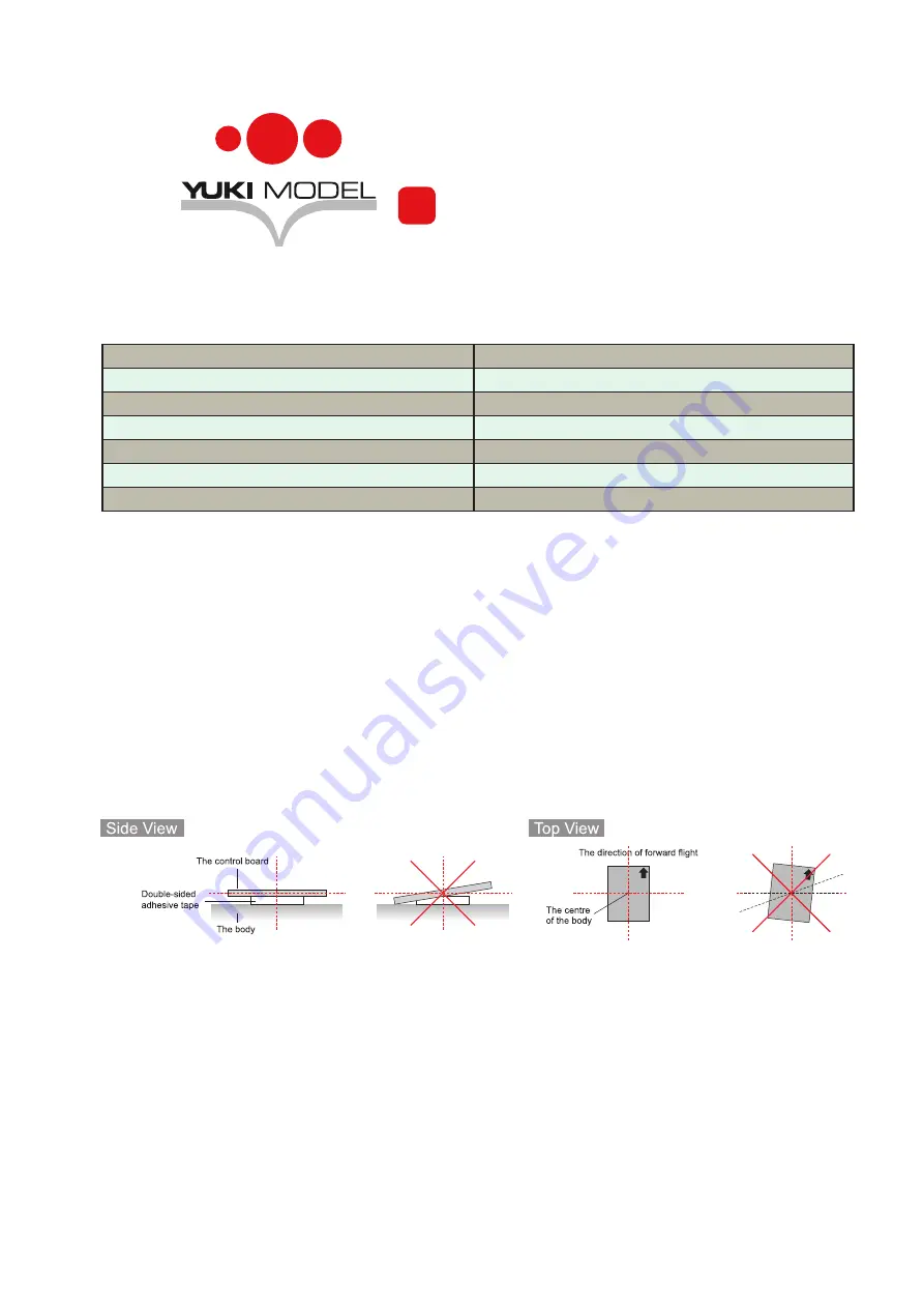
Das Board ist mittels doppelseitigem Klebeband
in der Rumpfmitte des Flugmodells zu befestigen.
Der auf der Platine aufgedruckte weiße Pfeil ist
in Flugrichtung auszurichten. Ein ungünstiger
oder ungenauer Einbau kann Einbußen der
Performance oder ein Fehlschlagen des Betriebs
zur Folge haben.
The board should be securely mounted in the
center of the fuselage of your plane by using a
double-sided tape. Please align the white arrow
printed on the PCB with forward flight direction
when mounting. Inappropriate or inaccurate
installation could decrease the performance of the
board or even result in complete failure.
Nach der Montage im Modell sind die Ruderkanäle
für Querruder, Höhenruder und Seitenruder vom
Empfänger (Rx) an die mit "IN" bezeichneten Pins
des Boards anzuschließen. Pin 1 = Quer, Pin 2
= Höhe, Pin 3 = Seite. Bei Verwendung von zwei
Querruderservos sind diese über ein Y-Kabel
anzuschließen. Bitte die Kabelfarben beachten.
After installation, connect the channels of aileron,
elevator and rudder from your receiver (Rx) to the
pins on the board marked "IN", pin 1 for aileron
servo, pin 2 for elevator servo and pin 3 for rudder
servo. You should use an Y extension cable
when using two aileron servos. When connecting,
please pay attention to the correct color of wires.
?
Specifications
Technische Daten
Spannungsbereich
4-6 V DC
PWM Output
50 Hz, 1.020-2.020 µs
Range
± 1.000 dps
Sample Rate
1 kHz
Betriebstemperatur
-40 °C to +85 °C
Abmessungen
18 x 40 mm
Gewicht
8 g
Montage
Installation
Summary of Contents for GYRO HERO
Page 1: ...GYRO HERO how to Anleitung...


