11
440 01 2020 01
Piping Insulation Guidelines
NOTE
: Use closed cell, neoprene insulation or equivalent. If Fiber-
glass or equivalent insulation is used it must have a vapor barrier.
Use R values of 7 up to 10
¢
, R--11 if exposure exceeds 10
¢
. If Fiber-
glass insulation is used, exterior to the structure, the pipe
MUST
be
boxed in and sealed against moisture.
1. .When the vent or combustion air pipe height above the roof
exceeds 30
²
, or if an exterior vertical riser is used on a hori-
zontal vent to get above snow levels, the exterior portion
MUST
be insulated.
2. When combustion air inlet piping is installed above a sus-
pended ceiling, the pipe
MUST
be insulated with moisture
resistant insulation such as Armaflex or other equivalent
type of insulation.
3. Insulate combustion air inlet piping when run in warm, humid
spaces such as basements.
Sizing Combustion Air and Vent Pipe
Consult Table 3 or Table 4 to select the proper diameter exhaust
and combustion air piping. Exhaust and combustion air piping is
sized for each furnace Btuh size based on total lineal vent length
(on inlet
or
outlet side), and number of 90
°
elbows required.
1.
Double Pipe Installation--
If installing as a direct--vent ap-
pliance, consult
Table 4
to select the proper diameter ex-
haust and combustion air piping. Exhaust and combustion
air piping is sized for each furnace Btuh size based on total
lineal vent length (on inlet
or
outlet side), and number of 90
°
elbows required.
2.
Single Pipe Installation--
If installing as a non--direct vent
appliance, (single outlet pipe and no inlet pipe) refer to
Table
3.
The table shows the maximum number of elbows allowed
with any given pipe diameter and length of run.
3.
Use of Elbows--
Two 45
°
elbows can be substituted for one
90
°
elbow. The elbow or elbows used for vent termination
outside the structure
ARE
counted, including elbows need-
ed to bring termination above expected snow levels. The el-
bow inside the furnace on the *9MPD
IS NOT
included in the
count.
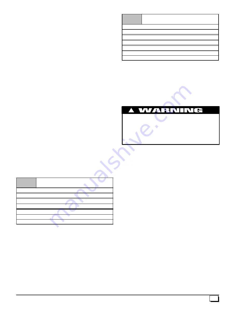
Table 3
Pipe Diameter Table
Single Piping ONLY
50,000 & 75,000 Btuh Furnaces
40
¢¢¢¢
& (5) 90
°
elbows with 2
²
PVC pipe or
100,000 Btuh Furnace
40
¢¢¢¢
& (5) 90
°
elbows with 3
²
PVC pipe
125,000 Btuh Furnace
40
¢¢¢¢
& (5) 90
°
elbows with 3
²
PVC pipe
Elbows are DWV Long Radius Type for 2
²
and 3
²
vents.
If more than five elbows are required, reduce the length of
both the inlet and exhaust pipes 5
¢
for each additional elbow
used.
NOTE:
It is allowable to use larger diameter pipe and fitting than
shown in the tables but
not
smaller diameters than shown.
Table 4
Pipe Diameter Table
Dual Piping ONLY
50,000 & 75,000 Btuh Furnaces
40
¢¢¢¢
& (5) 90
°
elbows with 2
²
PVC pipe or
100,000 Btuh Furnace
40
¢
& (5) 90
°
elbows with 3
²
PVC pipe
125,000 Btuh Furnace
40
¢
& (5) 90
°
elbows with 3
²
PVC pipe
Elbows are DWV Long Radius Type for 2
²
and 3
²
vents.
If more than five elbows are required, reduce the length of
both the inlet and exhaust pipes 5
¢
for each additional elbow
used.
*
Feet of pipe is whichever pipe run is the longest, either inlet
or
outlet side.
For
“Concentric Termination Kit”
Venting table, see
“
Section 11”
in this manual.
Vent Termination Clearances
CARBON MONOXIDE POISONING, FIRE AND EXPLO-
SION HAZARD.
Failure to properly vent this furnace can result in death,
personal injury and/or property damage.
Inlet and outlet pipes may NOT be vented directly
above each other.
!
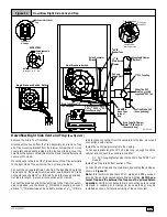
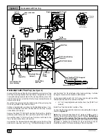
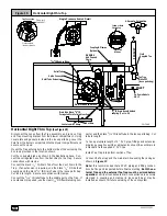
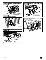
1. Determine termination locations based on clearances spe-
cified in following steps and as shown in
Figure 7,
Figure 19,
through
Figure 26.
For
“Concentric Termination Kit”
clearances, see Figure 46,
Figure 47, Figure 48, Figure 49 and Figure 50 in “
Section 10”
in this manual.
2. The vent termination must be located at least 12
²
above
ground or normally expected snow accumulation levels.
3. Do
NOT
terminate over public walkways. Avoid areas where
condensate may cause problems such as above planters,
patios, or adjacent to windows where steam may cause fog-
ging.
4. The vent termination shall be located at least 4
¢
horizontally
from any electric meter, gas meter, regulator, and any relief
equipment. These distances apply
ONLY
to U.S. installa-
tions.
5. The vent termination is to be located at least 3
¢
above any
forced air inlet located within 10
¢
; and at least 10
¢
from a
combustion air intake of another appliance, except another
direct vent furnace intake.
6. In Canada, the
Canadian Fuel Gas Code
takes precedence
over the preceding termination instructions.
Summary of Contents for 9MPT050F12A
Page 46: ...46 440 01 2020 01...


