background image

20

TAKE OFF

When there is suitable GPS signal for both the aircraft and ST16, and 

the aircraft is in Angle or Smart (chosen 'Follow') mode, the function 

of taking off the aircraft by one slide can be activated with the aircraft 

flat on the ground.

TAKEOFF

Model: H920 Plus

welcome,Pilot

12:27 AM 12

VOLTS

GPS

SAT

POS

ALT

G-SPD

DIS

N/A

N/A

N/AE

N/AN 

N/AV

N/Am

N/A KPH

N/Am

System  Settings

Pad

Channel Settings

Model Select

TASK    

CAMERA

GPS    

CALIBRATION

FOLLOW     

WATCH

ANGLE

G

Disabled

OBS

WAYPOINT

TAKEOFF

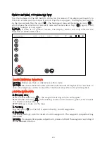
STEP 1) Press TASK/CAMERA, select TAKE OFF;

STEP 2) Slide the sliding block from left to right, the aircraft will climb vertically and 

begin to hover until it reaches about 6.6 feet high.

Connecting drone...

H:N/A

V.S:N/A

H.S:N/A

D:N/A

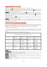
NOTICE: When the aircraft is in Home mode, the TAKE OFF function won't be 

activated; When the aircraft is in Angle or Smart (chosen 'Follow') mode, the TAKE 

OFF function won't be activated if the distance between the pilot and aircraft is less 

than 16.4 feet.

Summary of Contents for H920 PLUS

Page 1: ...V3 0 ...

Page 2: ... CHARGING THE LI ION ST16 BATTERY 11 ASSEMBLING THE H920 Plus 12 INSTALLING THE FLIGHT BATTERIES 13 FLIGHT CONTROLS 14 CONTROL RATE KNOB 14 RETRACTING AND LOWERING THE RETRACTABLE LANDING GEAR 15 LANDING 15 CONTROL RATE SLIDER 30 ATTACHING CGO4 GIMBAL CAMERA TO MULTICOPTER 31 LED STATUS INDICATION 32 PREPARING TO FLY 32 FLYING 33 COMPASS CALIBRATION 35 BINDING SINGLE MODE 35 CAMERA CONTROLS SINGLE...

Page 3: ...al multirotor aerial photography and videography platform Its unique and innovative features make it possible to capture amazing photographs and video footage for a variety of uses The modular aircraft platform is compatible with CGO4 Camera a 3 Axis Stabilized Gimbal System 2 ...

Page 4: ...ximum Flying Height Relative altitude 122m 400 ft Maximum Rotation Rate 100 s Maximum Roll Angle 35 Maximum Horizontal Speed GPS ON 40km h Radio Control Frequency Band 2 4GHz Operating Temperature Range 10 to 50 ST16 PERSONAL GROUND STATION Operating System Android Number of Channels 16 Control Transmission Distance Range Optimum Conditions Up to 1 Mile 1 6km Video link Frequency Band 5 8GHz WiFi ...

Page 5: ...bility of superficial injury WARNING Read the ENTIRE quick start guide and instruction manual to become familiar with the features of the product before operating Failure to operate the product correctly can result in damage to the product property and or cause serious injury WARNING This is a sophisticated consumer product It must be operated with caution and common sense and requires some basic ...

Page 6: ...h any worn and or damaged components parts etc including but not limited to damaged propellers rotor blades old batteries etc Never operate your aircraft in poor or severe weather conditions including heavy winds precipitation lightning etc Always operate your aircraft starting with a fully charged battery Always land as soon as possible after the first level low voltage battery warning or land im...

Page 7: ... imaging products there may be other enhancements available to suit a specific purpose 6 1 H920 Plus RTF Airframe 4 sets of Propeller Rotor Blade 2 A10 Charger 3 ST16 Transmitter and Personal Ground Station 4 4000mAh 6S 22 2V LiPo Battery 2pieces 5 ST16 LCD Screen Sun Shade Shield 6 ACCESSORY Box 1 2 3 4 5 6 ...

Page 8: ...embled or if the main components exhibit visible damage defects or missing parts Damage and or injury as well as violation of legal regulations caused by operating the model in a magnetic field e g high voltage lines electricity transformer stations radio towers mobile phone masts etc a strong wireless signal environment no fly zones poor visibility and in the event of vision impairments or other ...

Page 9: ...in reduced power flight duration or failure of the battery entirely LiPo cells should not be discharged to below 3 0V each under load Store the LiPo battery at room temperature and in a dry area for best results When charging transporting or temporarily storing the LiPo battery the temperature range should be from approximately 40 120 F 5 49 C Do not store the battery or aircraft in a hot garage c...

Page 10: ...et 4A no more than 8A For ProAction battery it is recommended to set 2A no more than 3A At the same time the battery cells number will start blinking press INC and DEC to change the value and press START ENTER to confirm your setting For the H920 Plus battery 6S should be selected For ProAction 4S should be selected Program Start Press and hold START ENTER for 3 seconds to start the program The ch...

Page 11: ...ger It will take approximately five 5 hours to charge a fully discharged not over discharged battery NOTICE To check the charge status of the ST16 simply tap the screen 2 times NOTICE The AC plug type will vary depending on the region in which the product was imported purchased AU Australian EU European UK United Kingdom US United States 10 ...

Page 12: ...ry and even fatal injury Mount the propellers on the motors properly and note the A and B printed on the motor arms This distinction between A and B refers to propeller A and B Mount propeller A on motor A and propeller B on motor B Press and rotate the propeller in the reverse direction the arrow indicates When a click is heard the propeller is successfully secured After securing the propeller ho...

Page 13: ...placed evenly within the two sides to balance the aircraft s center of gravity The voltage between each battery pack must be within 0 1V prior to connecting the batteries to the aircraft Be sure to use the included battery voltage meter STEP 3 Connect the flight battery to the relevant socket above the respective battery on the H920 PLUS using the EC3 blue polarity protected connector NOTICE The w...

Page 14: ...ative to the front nose of the aircraft and the angle of movement is determined by how far you push the stick away from the center position 13 The ST16 is equipped with 3 different flight modes which can be selected using the mode switch in the top right corner above the right joystick SMART MODE If the Flight Mode selection switch is fully up then the H920 Plus is in Smart Mode Although we recomm...

Page 15: ...tude level if the left stick is in the middle position WARNING If the H920 PLUS has not been mastered in Angle Mode accidents or fly away may result IMPORTANT NOTE Accidental damage and fly aways are not covered by the warranty RETRACTING AND LOWERING THE RETRACTABLE LANDING GEAR The H920 PLUS s landing gear is to keep it out of frame when a camera is attached Landing gear may be retracted by swit...

Page 16: ...eet Above Mean Sea Level and use the high speed rabbit position for the highest control rates best for experienced pilots and can only be used when flying below 5000 feet MSL Speed is variable between Slow and Fast modes 15 TS01 TS02 TS03 TS04 00 35 25 D R 0 System Setting Channel Setting Model Select 9 12 6V FSK WIFI Roll 120 Pitch 0 300M 125km h TS05 TS06 TS07 TS08 GPS VOL FSK WiFi CHA POS CHA P...

Page 17: ...uitable GPS signal lock over the home position except in instances of low battery where it will land itself PILOT LOCATION 13 26 ft 4 8m LANDING LOCATION 8m HOME HORIZONTAL DISTANCE FROM PILOT PILOT ADDITIONAL FUNCTIONS If the PAN mode of the gimbal camera is switched to Follow and Follow Pan Controllable modes the gimbal TILT angle will be adjusted as the same as the angle what the gimbal camera ...

Page 18: ...ion route by sliding the chosen one to the left SAVE Tap SAVE and the current mission route will be saved START Tap START and slide the icon H920 PLUS will fly back to waypoint 1 automatically BACK RESET LIST SAVE START When the pilot tap the the icon will become and the CCC function will be paused When tapped again the will become the copter will continue the CCC function Exit the function by tapp...

Page 19: ...RT and slide the icon push the aileron stick to the right or left The H920 PLUS will fly around the pilot ST16 with the distance between the start point and the pilot as the radius BACK Tap BACK to return to the previous interface NOTICE You can increase decrease radius by apply forward back on right stick You also can trim the gimbal pan position by adjusting pan control knob on ST16 under Follow ...

Page 20: ...ecreased by pushing forward backward on right stick NOTICE Adjust the Throttle Control joystick to change the height of the aircraft adjust the Aileron Control joystick to change the orbit direction of the aircraft When the pilot tap the the icon will become and the POI function will be paused When tapped again the will become the copter will continue the POI function Exit the function by tapping ...

Page 21: ...Channel Settings Model Select TASK CAMERA GPS CALIBRATION FOLLOW WATCH ANGLE G Disabled OBS WAYPOINT TAKEOFF STEP 1 Press TASK CAMERA select TAKE OFF STEP 2 Slide the sliding block from left to right the aircraft will climb vertically and begin to hover until it reaches about 6 6 feet high Connecting drone H N A V S N A H S N A D N A NOTICE When the aircraft is in Home mode the TAKE OFF function w...

Page 22: ...Google Map automatically The settings icon may also be tapped on the right top corner of the screen and then tap the icon to switch the map manually To download maps follow the steps below Model H920 Plus welcome Pilot 12 27 AM 12 VOLTS GPS SAT POS ALT G SPD DIS N A N A N AE N AN N AV N Am N A KPH N Am System Settings Pad Channel Settings Model Select TASK CAMERA GPS CALIBRATION FOLLOW WATCH ANGLE...

Page 23: ...g Connecting drone H N A V S N A H S N A D N A NOTICE The aircraft or the ST16 can be selected as the center of the location by tapping the icon on the screen There are two displaying modes of Google map Overlay Normal and Satellite Tap the map icon select the mode NOTICE Some areas are unable to display satellite maps due to map sampling availability from provider After the map is downloaded tap ...

Page 24: ...TE PLANNING FUNCTION NOTICE Make sure that no obstacle is within route NOTICE We recommend that the planned route should be higher than 16 4 feet In case of emergency switch to any other mode can stop the route planning task ADDING WAYPOINTS A Drawing Line STEP 1 Press the icon the waypoint setting column will appear STEP 2 Press the icon in the setting column and it will turn green which means it...

Page 25: ... waypoints Press any waypoint on the mission or any figure on the top left of the screen The mission may be configured for a single waypoint Settings for single waypoint 1 Relative altitude minimum altitude is 16 4 ft 5m default altitude is 65 6 ft 20m 2 Speed range from 9KhH 0 06 mph to 30KmH 18 6 mph default speed is 14 3KmH 8 9 mph 3 Settings for Gimbal Control in Pan and Tilt Directions 24 Dif...

Page 26: ...ll remain the last setting angle 2 Tilt Point to the POI only when the Custom Waypoint gimbal pan mode is selected in Global Settings The gimbal will tilt and automatically point the camera lens to the POI Manual The operation identical to the gimbal tilt control in angle mode The left slider on the ST16 controls gimbal tilt angle The control range operates from 0 to 90 Custom At each waypoint the...

Page 27: ...lected waypoint the camera will take a photo Record Choose Record and then select Add Action When the aircraft reaches the selected waypoint the camera will begin to record video The record time is manually set within a range of 1s to 60s STEP 3 After all settings are completed choose YES Settings will be saved IMPORTANT NOTE The system does not save any setting by default Choose OK to save settin...

Page 28: ... hover loiter Cycle Return to the first waypoint straightly and fly along waypoints one by one and cycle IMPORTANT NOTE The pilot should set relative altitude and speed for all waypoints first then create the mission route The operation for all waypoints will be valid and stored If the mission route is created prior to setting altitude and speed the mission parameters will not be stored NOTICE Cha...

Page 29: ...y be set Touch all desired on the map and the system will automatically link them to form the geo fence NOTICE Currently 20 points are limited to a maximum of 20 points All points should be set in order NOTICE When using a default geo fence press and hold any vertex to adjust its shape After setting creating the geo fence switch to Angle mode Press start and then slide the sliding block The geo fe...

Page 30: ... start stop button until the propellers begin to spin Press the icon and slide the sliding block The aircraft will climb to the altitude of 5m 16 4 feet and hover loiter The icon will become a Point to Land icon Select and tap on the screen at the desired landing point NOTICE When the altitude of the aircraft is lower than 10m 32 8 it will climb to 10m 32 8 vertically first then fly to the point a...

Page 31: ... damping plate relative to the direction of H920 Plus power connection port STEP 2 Mount the gimbal thumb screws and lock washers 4 pcs to the gimbal and rotate the screws until they re secured into the gimbal damping plate NOTICE The front of the gimbal should be installed in the direction of the nose of H920 Plus NOTICE Use the dedicated lock washers when rotating the screws STEP 3 Connect the g...

Page 32: ...links red rapidly 5 times per second First Level low Voltage Battery Warning Flashes red green and blue every 3 seconds Second Level low Voltage Battery Warning Flashes red green and blue continuously GPS Disabled Flashes purple 1 flash per second ST16 with GPS lock Blinks white every three seconds Enter Task function Blink green and purple slowly 1 time per second LED STATUS INDICATIONS FOR CALIB...

Page 33: ...rior to powering the H920 PLUS and ALWAYS turn off power down the H920 PLUS prior to turning off the ST16 If the main LED status indicator flashes yellow the compass calibration procedure will need to be executed If the main LED status indicator is flashing blue double check that the ST16 is powered on and set to the correct model memory If the main LED status indicator is still flashing blue re b...

Page 34: ...en the aircraft and make sure they are connected correctly If they are not connected correctly the telemetry data will not display on the screen STEP 2 Tap the GPS CALIBRATION icon on the ST16 screen and choose COMPASS GPS CALIBRATION STEP 3 For best results remove propellers if installed Lift H920 PLUS airframe straight and level When one beep is heard turn the aircraft forward as shown by the re...

Page 35: ... above until you hear the acknowledgement tone If the calibration has been successful an acknowledgement tone will sound the same tone heard when the H920 PLUS aircraft is powered on and the H920 PLUS will restart IMPORTANT NOTE If calibration has failed the Main LED Status Indicator will be solid white the calibration process must be repeated If the calibration continues to fail either the calibr...

Page 36: ...lso be used to bind a new aircraft Long press the original model icon and choose Copy from the sub menu Repeat the above steps NOTICE If an error message is displayed in camera mode tap OK to enter camera mode Select CGO4 and select the return button to return to the control interface GIMBAL CAMERA TILT CONTROL There is a gimbal tilt mode switch on ST16 labelled S1 When the switch is in up middle ...

Page 37: ...er the aircraft s movements When the switch is in the middle position the gimbal camera is in Follow Pan Controllable Mode the gimbal camera will adjust its pan direction per the aircraft s movements Use the Pan Control Knob to set the pan position of the gimbal camera When the switch position is down the gimbal camera is in Global Mode The pan direction of the gimbal camera will be fixed regardle...

Page 38: ... radiate radio frequency energy and if not installed and used in accordance with the instructions may cause harmful interference to radio communications However there is no guarantee that interference will not occur in a particular installation If this equipment does cause harmful interference to radio or television reception which can be determined by turning the equipment off and on the user is ...

Page 39: ...e aux CNR d Industrie Canada applicables aux appareils radio exempts de licence L exploitation est autorisée aux deux conditions suivantes 1 l appareil ne doit pas produire de brouillage et 2 l utilisateur de l appareil doit accepter tout brouillage radioélectrique subi même si le brouillage est susceptible d en compromettre le fonctionnement This equipment complies with IC RSS 102 radiation expos...

Reviews: