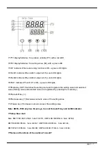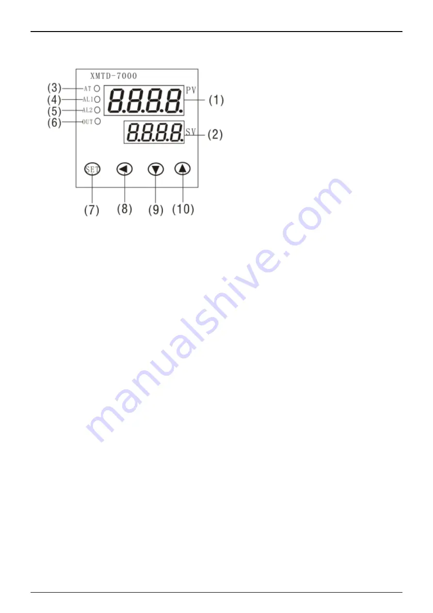
?1?PV displayIndicates the process variable (PV) with a red LED.
?2?SV displayIndicates the setting value (SV) with a green LED.
?3?AT indicator When auto tuning function is ON, a green LED lights.
?4?ALM1 indicator When ALM1 output is ON, a red LED lights.
?5?ALM2 indicator When ALM2 output is ON, a red LED lights.
?6?OUT indicator When OUT is ON, a green LED lights.
?7?Mode key (SET) Switches the setting mode and registers the setting value and selected
value.(Setting value and selected value are registered by pressing the mode key.)
?8?Data shift key (<)
?9?Decrease key (?)Decreases numeric value of the setting value
?10?rease key (?)Increases numeric value of the setting value.
Note: XMTG-7000 only has three keys, has not Data shift key and ALM2 indicator.
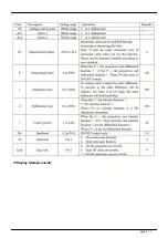
??Setup flow chart
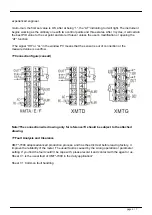
Size: XMT:160×80×125mm hole:152×76; XMTA:96×96×85mm hole: 92×92;
XMTE:48×96×85mm hole: 44×92; XMTF:96×48×85mm hole: 92×44;
XMTD:72×72×85mm hole: 68×68; XMTG:48×48×110mm hole: 44×44;
??Name and functions of the sections?consult?
page 3 / 7

