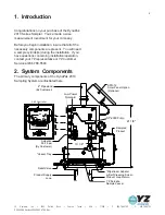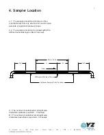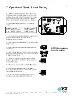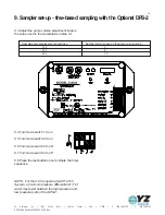
DP-2010RX Version 06042001 ATEX Rev.
YZ Systems, Inc. • 3101 Pollok Drive • Conroe, Texas • USA • 77303 • P: 936.788.5793 • F: 936.788.5720
17
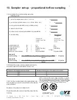
10.4 Calculate the counter setting using the
following chart:
1. your pump displacement (from .1 to .4cc’s)
=
a.__________
2. your sample cylinder volume in cc’s (300cc, 500cc, etc.)
=
b.__________
3. average flow rate (MMCF per day or MCM per day)
=
c.__________
4. sample period in days
=
d.__________
5. pulses/volume metered (pulses/MMCF or pulses/MCM)
=
e.__________
6. counter setting
=
a x c x d x e
(b)
Example #1:
English Gas Flow
Units
Example #2:
Metric Gas Flow
Units
10.5 Adjust the pump volume adjustment knob to
the value used in the calculation in step 10.4.
Sample pump displacement per stroke
.1cc
.2cc
.4cc
Number of turns open on the pump volume knob
3
6
12
10.6 Turn the counter dials to the appropriate num-
ber of pulses you want to count before the sample
pump strokes.
Example: 20 pulses; turn dials to 20.
Press the test button once to load the value into the
memory.
NOTE: If the calculated counter setting is less than 1 or greater
than 99, the pulses per volume metered will need to be adjusted.
This can be programmed in most flow meters to the desired rate.
If the calculated counter setting is less than 1, increase the pulses
per volume metered. If the calculated counter setting is greater
than 99, decrease the pulses per volume metered volume.
3
2
0
9
6
8
7
1
3
2
5
4
0
9
1
6
7
8
5
4
pump displacement
(a.)
=
.2cc
.2cc
sample cylinder size
(b.)
=
300cc
300cc
average flow rate
(c.)
=
10 MMCF per day
10MCM/day
sample period
(d.)
=
30 days
30 days
pulses per volume metered
(e.)
=
100 pulses/MMcf
100 pulses/MCM
Example #1
counter setting = .2cc x 10 MMcf per day X 30 days X 100 pulses per MMcf =
20 pulses
300 cc
Example #2
counter setting = .2cc x 10 MCM per day X 30 days X 100 pulses per MCM =
20 pulses
300 cc
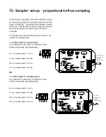
10. Sampler set-up - proportional-to-flow sampling


