background image

YZ Systems, Inc. • 3101 Pollok Drive • Conroe, Texas • USA • 77303 • P: 936.788.5593 • F: 936.788.5720

Page 31

DP-2010FU  ver.04202004

SSSSS

ECTION

ECTION

ECTION

ECTION

ECTION

 9:

 9:

 9:

 9:

 9:  S

  S

  S

  S

  S

Y

YY

Y

YSTEM

STEM

STEM

STEM

STEM

 O

 O

 O

 O

 O

PERA

PERA

PERA

PERA

PERATION

TION

TION

TION

TION

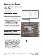
Preparing The System for Operation

1.  When all of the tubing connections have
     been completed, close the purge valve on the
     front of the sampler probe body.  Open the
     sample probe supply valve to allow pipeline
     pressure into the sampler, 

refer to Section 8,

    page 27.

  Check all connections using a liquid

    leak detector.

2.  Adjust the filter/regulator from the following
     ranges, 

refer to Section 8, page29

:

Pipeline Pressure

Actuation Pressure

Under 700 psig (48 Bar)

50 psig (3.5 Bar)

Over 700 psig   (48 Bar)

65 psig (4.5 Bar)

3.  Turn the stroke adjustment knob on the top of
     the pump counterclockwise to set the pump
     displacement at .4 cc/stroke,

     refer to Section 8, page28

.

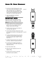
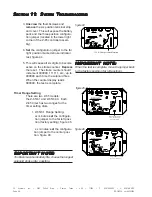
4.  Move all of the mode switches on the Z-65 to
     their off positions, figure 20.

5.  Move both timer/counter dials to the 0 posi-
     tion (00 minutes), figure 21.

6.  Move mode switches 1, 2 and 3 to the on
     position.  The pump will begin stroking once
     every 2 seconds in a diagnostic test mode,
     figure 22.

7.  Allow the sampler to operate until the pipeline
     pressure plus 100 psi (6.9 Bar) is achieved
     at the sample discharge.

8.  Return the mode switches to their off posi-
     tions, figure 23.

9.  Check all connections from the sampler
     discharge to the connection on the sample
     cylinder using a liquid leak detector.

10.If no leaks are found, the pump and tubing
     should be considered tested and functional.

NOTE:  Black indicates
the switch position.

Mutual

System

Approved

Factory

figure 19

figure 20

figure 23

figure 22

figure 21

Summary of Contents for DynaPak DP-2010FU

Page 1: ...DynaPak GasSampler S Y S T E M S U P P O R T M A N U A L DP 2010FU ...

Page 2: ...DP 2010FU INSTRUCTION OPERATING MANUAL Version 04202004 ...

Page 3: ...tem Flow Schematic 6 Standard System Mounting 7 Standard System Connections 8 Optional DPS 2 Installation 9 Section 3 Sample Vessel Installation 11 Variable Pressure Constant Volume Cylinders 11 Link Plus 11 Section 4 System Control Electronics 13 Overview 13 Section 5 Programming for Proportional to Flow Operation 15 Setting Operator Input Parameters 15 Section 6 Programming For Proportional To T...

Page 4: ...41 ForAdditional Help 41 Step by Step Resolution 41 Battery Power 42 Battery Power Troubleshooting Steps 42 Z 65 Counter Mode 43 Z 65 Counter Mode Troubleshooting Steps 43 Z 65 Timer Mode 44 Z 65 Timer Mode Troubleshooting Steps 45 Appendix A Illustrations 49 DP 2000 Sample Pump Assembled 49 DP 2000 Sample Pump Exploded View 50 Filter Regulator Assembled 51 Filter Regulator Exploded View 52 Link P...

Page 5: ...bat PDF format will be highlighted further in blue italic text indicating the copy retains a hyperlink to the referenced item Measurement units are listed in italic parenthesis text following their US standard equivalent As an example for defining a distance 15 4 5 meters is how the text will appear throughout the manual Items that require action for example the pressing of a key for programming t...

Page 6: ... OperationSpecifications Maximum Output 5 760 cc day 5 76 liters day Maximum Operating Pressure 1 500 psig 124 Bar g Pump Displacement 2 4 cc Stroke Operating Temp Range 0 to 140 degrees F 17 C to 60 C Power Supply Internal Battery Pack Flow Signal Dry Contact or Voltage Pulse Catalytic Heater Start Voltage 12 VDC The External Power Option can be used in lieu of the internal battery pack The Exter...

Page 7: ...id output is activated is recorded by the onboard LCD stroke indicator B Time based sampling with the YZ differential pressure switch DPS 2 this mode of operation is similar to the time based sampling mode except that the DPS 2 converts a differential pressure signal to an electrical signal that the Z 65 timer uses to determine if flow is present in the pipeline In effect the DPS allows the Z 65 t...

Page 8: ... 12 charger regulator module and internal 12V 5 Amp hour battery pack SC Spun Vessel portable DOT approved 1800 psi maximum working pressure sample vessels Available in 300 and 500 cc sizes KK 1 KK 2 KK 3 carrying cases for DuraSites that meet DOT requirements for transporting portable sample vessels 1 4 stainless steel tubing Dielectric Isolator Union These should be installed in every tubing lin...

Page 9: ... Pump figure 2 Probe mounted pneumati cally actuated DP 2000 Sample Pump Filter Regulator figure 2 Stainless Steel requlator capable of reducing pressure from line pressure of up to 1500 psi down to system supply pressures in one step Low Power Solenoid figure 2 provides interface between the Z 65 Electronic Controller and the Pump Pneumatic actuation Z 65 Controller Enclosure figure 1 Provides a ...

Page 10: ...3 F 936 788 5720 Page 6 DP 2010FU ver 04202004 S S S S SECTION ECTION ECTION ECTION ECTION 2 2 2 2 2 S S S S SY Y Y Y YSTEM STEM STEM STEM STEM I I I I INST NST NST NST NSTALLA ALLA ALLA ALLA ALLATION TION TION TION TION System Flow Schematic figure 2 To Catalytic Heater ...

Page 11: ...from any device which could cause aerosols or significant pressure drops 2 The sampler should not be located within the defined meter tube region AGA 3 manual A The number of unobstructed straight pipe diameters upstream see AGA 3 manual B The number of unobstructed straight pipe diameters downstream see AGA 3 manual A The number of unobstructed straight pipe diameters upstream see AGA 3 manual B ...

Page 12: ...veandpurgevalveareclosed f After pipeline pressure has been applied to the sampler check the probe body pipeline connec tion using a liquid leak detector CA CA CA CA CAUTION UTION UTION UTION UTION Incorrect operation of valves over tightening can result in damage to the valve components isolation valve bonnet assembly which might result in the valve stem being screwed out of the probe body This o...

Page 13: ...gh pressure supply valve without ensuring that the equalization valve is open Failure to do so may damage the DPS 2 s internal components d Open the other supply valve e Close the equalization valve f Run the free end of the DPS 2 cable through the cable entry connector located on the upper left side on the DynaPak 2010 enclosure g Connect the DPS 2 cable as shown in the diagram h Tighten the cabl...

Page 14: ...SA 77303 P 936 788 5593 F 936 788 5720 Page 10 DP 2010FU ver 04202004 S S S S SECTION ECTION ECTION ECTION ECTION 2 2 2 2 2 S S S S SY Y Y Y YSTEM STEM STEM STEM STEM I I I I INST NST NST NST NSTALLA ALLA ALLA ALLA ALLATION TION TION TION TION Notes ...

Page 15: ...Constant Volume Cylinders Spun cylinders may be installed in a vertical position on the DynaPak SC vessel manifold Stainless steel tubing and fittings from the sample discharge port of the sampler are pre installed to the product end of the sample cylin der when installed in this manner LinkPlus Install the optional LinkPlus directly into the sample discharge port of the sampler Use stainless stee...

Page 16: ... 5593 F 936 788 5720 Page 12 DP 2010FU ver 04202004 S S S S SECTION ECTION ECTION ECTION ECTION 3 3 3 3 3 S S S S SAMPLE AMPLE AMPLE AMPLE AMPLE V V V V VESSEL ESSEL ESSEL ESSEL ESSEL I I I I INST NST NST NST NSTALLA ALLA ALLA ALLA ALLATION TION TION TION TION Notes ...

Page 17: ...very time a sample is required either Proportional To Flow or Time SAFETY NO SAFETY NO SAFETY NO SAFETY NO SAFETY NOTES TES TES TES TES Always use extreme care when performing mainte nance on Sampling Systems Always take necessary measures to assure that electrical classification in the area is considered before and during all repairs and that necessary steps are taken to maintain proper electrica...

Page 18: ...593 F 936 788 5720 Page 14 DP 2010FU ver 04202004 S S S S SECTION ECTION ECTION ECTION ECTION 4 4 4 4 4 S S S S SY Y Y Y YSTEM STEM STEM STEM STEM C C C C CONTR ONTR ONTR ONTR ONTROL OL OL OL OL E E E E ELECTR LECTR LECTR LECTR LECTRONICS ONICS ONICS ONICS ONICS Notes ...

Page 19: ...lled by the host computer or output device that will give an input pulse to the Z 65 controller 1 Determine if the incoming input is either a dry contact or voltage pulse 2 If the input is a dry contact a Terminate the incoming connections to the Z 65 terminal strip see illustration b Turn mode switch 1 to on c Turn mode switch 2 to off d Turn mode switch 3 to on e Turn mode switch 4 to off OR 3 a...

Page 20: ...mp displacement per stroke 1cc 2cc 4cc Number of turns open on the pump volume knob 3 6 12 6 Turn the counter dials to the appropriate num ber of pulses you want to count before the sample pump strokes Example 20 pulses turn dials to 20 Press the test button once to load the value into the memory pump displacement a 2cc 2cc sample cylinder size b 300cc 300cc average flow rate c 10 MMCF per day 10M...

Page 21: ...ION ECTION ECTION ECTION ECTION 5 5 5 5 5 P P P P PR R R R ROGRAMMING OGRAMMING OGRAMMING OGRAMMING OGRAMMING FOR FOR FOR FOR FOR P P P P PR R R R ROPOR OPOR OPOR OPOR OPORTION TION TION TION TIONAL AL AL AL AL T T T T TO O O O O F F F F FL L L L LO O O O OW W W W W O O O O OPERA PERA PERA PERA PERATION TION TION TION TION Notes ...

Page 22: ...ION ECTION ECTION ECTION ECTION 5 5 5 5 5 P P P P PR R R R ROGRAMMING OGRAMMING OGRAMMING OGRAMMING OGRAMMING FOR FOR FOR FOR FOR P P P P PR R R R ROPOR OPOR OPOR OPOR OPORTION TION TION TION TIONAL AL AL AL AL T T T T TO O O O O F F F F FL L L L LO O O O OW W W W W O O O O OPERA PERA PERA PERA PERATION TION TION TION TION Notes ...

Page 23: ...le rate from step 1 3 2 0 9 6 8 7 1 3 2 5 4 0 9 1 6 7 8 5 4 12 400 18 36 60 9 13 27 45 3 6 4 9 18 9 15 30 300 200 100 Number of turns open on pump stroke knob sample pump displacement per stroke 1000 cc 500 cc 300 cc Sample cylinder volumes Sample rate minutes IMPOR IMPOR IMPOR IMPOR IMPORT T T T TANT NO ANT NO ANT NO ANT NO ANT NOTE TE TE TE TE To obtain maximum battery life choose the longest ti...

Page 24: ...L AL AL AL AL T T T T TO O O O O T T T T TIME IME IME IME IME O O O O OPERA PERA PERA PERA PERATION TION TION TION TION 4 Turn mode switch 1 to on 5 Turn mode switch 2 to on 6 Turn mode switch 3 to on 7 Turn mode switch 4 to off 8 Press the test button once to initiate the timer sequence 3 Adjust the pump volume adjustment knob to the value used in the calculations in step 1 Number of turns open o...

Page 25: ...SECTION ECTION ECTION ECTION ECTION 6 6 6 6 6 P P P P PR R R R ROGRAMMING OGRAMMING OGRAMMING OGRAMMING OGRAMMING FOR FOR FOR FOR FOR P P P P PR R R R ROPOR OPOR OPOR OPOR OPORTION TION TION TION TIONAL AL AL AL AL T T T T TO O O O O T T T T TIME IME IME IME IME O O O O OPERA PERA PERA PERA PERATION TION TION TION TION Notes ...

Page 26: ...SECTION ECTION ECTION ECTION ECTION 6 6 6 6 6 P P P P PR R R R ROGRAMMING OGRAMMING OGRAMMING OGRAMMING OGRAMMING FOR FOR FOR FOR FOR P P P P PR R R R ROPOR OPOR OPOR OPOR OPORTION TION TION TION TIONAL AL AL AL AL T T T T TO O O O O T T T T TIME IME IME IME IME O O O O OPERA PERA PERA PERA PERATION TION TION TION TION Notes ...

Page 27: ...le 12 400 18 36 60 9 13 27 45 3 6 4 9 18 9 15 30 300 200 100 Number of turns open on pump stroke knob sample pump displacement per stroke 1000 cc 500 cc 300 cc Sample cylinder volumes Sample rate minutes 18 minutes 3 2 0 9 6 8 7 1 3 2 5 4 0 9 1 6 7 8 5 4 IMPOR IMPOR IMPOR IMPOR IMPORT T T T TANT NO ANT NO ANT NO ANT NO ANT NOTE TE TE TE TE To obtain maximum battery life choose the longest time int...

Page 28: ...ump volume adjustment knob to the value used in the calculations in step 1 4 Turn mode switch 1 to on 5 Turn mode switch 2 to on 6 Turn mode switch 3 to off 7 Turn mode switch 4 to off 8 Press the test button once to initiate the timer sequence Number of turns open on the pump volume knob 3 6 12 Sample pump displacement per stroke 1cc 2cc 4cc System Mutual Approved Factory IMPOR IMPOR IMPOR IMPOR ...

Page 29: ... S S S S SECTION ECTION ECTION ECTION ECTION 7 7 7 7 7 P P P P PR R R R ROGRAMMING OGRAMMING OGRAMMING OGRAMMING OGRAMMING FOR FOR FOR FOR FOR P P P P PR R R R ROPOR OPOR OPOR OPOR OPORTION TION TION TION TIONAL AL AL AL AL T T T T TO O O O O T T T T TIME IME IME IME IME W W W W W DPS 2 DPS 2 DPS 2 DPS 2 DPS 2 Notes ...

Page 30: ... S S S S SECTION ECTION ECTION ECTION ECTION 7 7 7 7 7 P P P P PR R R R ROGRAMMING OGRAMMING OGRAMMING OGRAMMING OGRAMMING FOR FOR FOR FOR FOR P P P P PR R R R ROPOR OPOR OPOR OPOR OPORTION TION TION TION TIONAL AL AL AL AL T T T T TO O O O O T T T T TIME IME IME IME IME W W W W W DPS 2 DPS 2 DPS 2 DPS 2 DPS 2 Notes ...

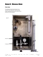
Page 31: ... ECTION ECTION 8 8 8 8 8 M M M M MECHANICAL ECHANICAL ECHANICAL ECHANICAL ECHANICAL S S S S SY Y Y Y YSTEM STEM STEM STEM STEM Overview The DynaPak mechanical system figure 18 are composed of the sample pump and filter regulator These components of the system are shown here and described in the following pages figure 18 FilterRegulator SamplePump ...

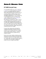
Page 32: ...50 located on the top of the DP 2000 pump Adjustment is simple Turn the volume adjustment knob clockwise to increase the pump volume displacement per stroke or turn the volume adjustment knob counter clock wise to decrease the pump volume displacement per stroke Final control of the volume of sample to be gathered during the sample cycle period is achieved by the Z 65 controller This pump has inte...

Page 33: ... Regulator refer to Appendix A page 51 is a stainless steel filtered regulator to supply the supply gas required to actuate the sample pump It is capable of providing actua tion pressure from pipeline pressures to required actuation pressures in a single dependable step Maintenance is minimal but is certainly depen dant on gas quality Should the gas supplied to the filter regulator require signifi...

Page 34: ...e Texas USA 77303 P 936 788 5593 F 936 788 5720 Page 30 DP 2010FU ver 04202004 S S S S SECTION ECTION ECTION ECTION ECTION 8 8 8 8 8 M M M M MECHANICAL ECHANICAL ECHANICAL ECHANICAL ECHANICAL S S S S SY Y Y Y YSTEM STEM STEM STEM STEM Notes ...

Page 35: ...8 Bar 65 psig 4 5 Bar 3 Turn the stroke adjustment knob on the top of the pump counterclockwise to set the pump displacement at 4 cc stroke refer to Section 8 page28 4 Move all of the mode switches on the Z 65 to their off positions figure 20 5 Move both timer counter dials to the 0 posi tion 00 minutes figure 21 6 Move mode switches 1 2 and 3 to the on position The pump will begin stroking once e...

Page 36: ...will return to the extended position but there will be a significant reduction in spring tension 14 Wait five minutes or until catalyst reaction begins as indicated by a rapid rise in the heater face temperature 14 Disconnect the electrical supply IMPOR IMPOR IMPOR IMPOR IMPORT T T T TANT NO ANT NO ANT NO ANT NO ANT NOTE TE TE TE TE If jumper cables are used disconnect them from the power source F...

Page 37: ...e Texas USA 77303 P 936 788 5593 F 936 788 5720 Page 33 DP 2010FU ver 04202004 S S S S SECTION ECTION ECTION ECTION ECTION 9 9 9 9 9 S S S S SY Y Y Y YSTEM STEM STEM STEM STEM O O O O OPERA PERA PERA PERA PERATION TION TION TION TION Notes ...

Page 38: ...e Texas USA 77303 P 936 788 5593 F 936 788 5720 Page 34 DP 2010FU ver 04202004 S S S S SECTION ECTION ECTION ECTION ECTION 9 9 9 9 9 S S S S SY Y Y Y YSTEM STEM STEM STEM STEM O O O O OPERA PERA PERA PERA PERATION TION TION TION TION Notes ...

Page 39: ...preventative maintenance schedule implemented should consider the application of the sampler Many of these considerations include the weather environment the condition of the actuation gas the product condition and quality and the pump stroke frequency All of these issues must be considered when establishing a preven tative maintenance schedule Recommended Maintenance Schedule Monthly Inspection 1...

Page 40: ...ting 5 Unscrew the pump body by hand from the inlet check valve assembly Separation at this point is recommended to maintain proper tubing location and alignment between the pump body and the probe body Do not remove the inlet check valve body from the manifold unless cleaning is necessary To replace the inlet check valve o ring carefully cut the o ring off the head of the dart and stretch the new...

Page 41: ...ody bushing into the bottom of the pump body figure 26 11 Insert all other bushings springs and o rings in their respective sequence on the plunger shaft figure 26 12 Carefully install assembly into the top of the pump body and screw the actuator assem bly onto the pump body Tighten firmly by Hand ONLY 13 Install the pump assembly on the inlet valve assembly Tighten firmly by Hand ONLY 14 Connect ...

Page 42: ...E ANCE Replacing a Depleted Battery 1 Remove the four thumb screws cover plate and orange terminal connector 2 The battery is located in the lower left hand corner of the Z 65 controller assembly 3 Unclip the battery plug from the battery receptacle 4 Replace the depleted battery with a fresh battery pack part No E3 2001 Refer to figure 27 to assure proper battery wire place ment in the Z 65 enclo...

Page 43: ... USA 77303 P 936 788 5593 F 936 788 5720 Page 39 DP 2010FU ver 04202004 S S S S SECTION ECTION ECTION ECTION ECTION 10 10 10 10 10 S S S S SY Y Y Y YSTEM STEM STEM STEM STEM M M M M MAINTEN AINTEN AINTEN AINTEN AINTENANCE ANCE ANCE ANCE ANCE Notes ...

Page 44: ... USA 77303 P 936 788 5593 F 936 788 5720 Page 40 DP 2010FU ver 04202004 S S S S SECTION ECTION ECTION ECTION ECTION 10 10 10 10 10 S S S S SY Y Y Y YSTEM STEM STEM STEM STEM M M M M MAINTEN AINTEN AINTEN AINTEN AINTENANCE ANCE ANCE ANCE ANCE Notes ...

Page 45: ...0 653 9435 T 1 936 788 5526 International Calls F 1 936 788 5720 Em Service yzhq com SAFETY NO SAFETY NO SAFETY NO SAFETY NO SAFETY NOTES TES TES TES TES Always use extreme care when performing mainte nance on Sampling Systems Always take necessary measures to assure that electrical classification in the area is considered before and during all repairs and that necessary steps are taken to maintai...

Page 46: ... Power Troubleshooting Steps 1 Set the mode switches as follows figure 28 Position 1 2 and 3 on 2 Set the time switches to the 01 position figure 29 This will set the solenoid output rate to one actuation every one minute based on the factory set time range for the Z 65 model refer to figure 45 page 46 3 Depress the test switch to test the battery A green LED will illuminate if the battery is good...

Page 47: ...ode switches as follows refer to figure 31 Position 1 and 3 on 2 and 4 off 2 Set the count switches to 00 to enter the diagnostic mode refer to figure 32 This mode enables the user to determine if the proper input pulses are being received at the count input ter 3 A Dry Contact Input mode switch 4 should be in the off position refer to figure 34 Depress the test switch and hold A red LED should il...

Page 48: ...press the test switch and hold A green LED should illuminate When the voltage pulse input is received at the count input ter 3 the red LED will turn on and off and the green LED will illuminate again This will normally occur very quickly and give the appearance that the red LED blinks on when the pulse input is received and removed figure 36 Factory System Approved Mutual figure 36 Z 65 Timer Mode...

Page 49: ...e switches as follows figure 39 Position 1 and 2 on Position 3 and 4 off 2 Set the time dials to 00 to enter the diagnostic mode figure 40 3 This mode enables the operator to determine if the DPS is operating properly This is accomplished by depressing and holding the test switch If the DPS is sensing flow in the pipeline the green LED should illumi nate If flow is not present the red LED should i...

Page 50: ...time the solenoid fires When the counter display reads 999999 the test is complete Timer Range Setting There are two Z 65 models the Z 65 6 1 and Z 65 6 03 Each Z 65 timer has two ranges for the timer setting dials 1 Z 65 6 1 Range Setting xx minutes set the configura tion jumper to the far left posi tion factory setting figure 45 x x minutes set the configura tion jumper to the center posi tion f...

Page 51: ...ange Setting x x minutes set the configuration jumper to the far left position factory setting figure 47 xx minutes set the configuration jumper to the center position figure 48 Mutual System Approved Factory factory positioned for 1 9 9 counts x x Jumper switch location Jumper switch location for 03 99 counts xx Mutual System Approved Factory IMPOR IMPOR IMPOR IMPOR IMPORT T T T TANT NO ANT NO AN...

Page 52: ... 936 788 5593 F 936 788 5720 Page 48 DP 2010FU ver 04202004 S S S S SECTION ECTION ECTION ECTION ECTION 11 11 11 11 11 S S S S SY Y Y Y YSTEM STEM STEM STEM STEM T T T T TR R R R ROUBLESHOO OUBLESHOO OUBLESHOO OUBLESHOO OUBLESHOOTING TING TING TING TING Notes ...

Page 53: ...SA 77303 P 936 788 5593 F 936 788 5720 Page 49 DP 2010FU ver 04202004 A A A A APPENDIX PPENDIX PPENDIX PPENDIX PPENDIX A A A A A I I I I ILL LL LL LL LLUSTRA USTRA USTRA USTRA USTRATIONS TIONS TIONS TIONS TIONS DynaPak 2000 Pump Assembled Figure 49 ...

Page 54: ...Assembly P N B1 0002 O Ring 010 P N A5 1010 Volume Adjustment Knob matic Fitting P N A1 0113 lume Adjustment Spring ume Adjustment Detent per Diaphragm Housing Diaphragm P N B1 0003 P N C3 0005 P N B1 0030 Set Screw P N C0 0096 P N C0 0014 Cap Screw 6 Each P N B1 0020 P N C0 0026 Inlet Screen P N C4 0006 P N C3 0008 Inlet Check Valve Spring Inlet Check Valve Spring Guide Nut Body Bushing P N B1 00...

Page 55: ...SA 77303 P 936 788 5593 F 936 788 5720 Page 51 DP 2010FU ver 04202004 A A A A APPENDIX PPENDIX PPENDIX PPENDIX PPENDIX A A A A A I I I I ILL LL LL LL LLUSTRA USTRA USTRA USTRA USTRATIONS TIONS TIONS TIONS TIONS YZ Filter Regulator Assembly Figure 51 ...

Page 56: ...3 Pressure Gauge P N C3 0009 P N C3 0011 Lower Spring Lower Dart A3 0073 O Ring 012 Retaining Nut P N A5 1012 Seat P N A3 0072 Upper Dart P N A3 0071 Upper Spring P N C3 0010 P N A3 0070 Piston P N A3 0069 Piston Spring Spring Cap P N A3 0068 P N A3 0067 Bonnet Pneumatic Fitting P N A1 0113 P N A8 0016 Adjustment Screw P N A3 0066 O Ring 120 Filter Housing P N A3 0076 Filter Element P N C4 0004 Fi...

Page 57: ...bly Valve Seat P N A3 0063 P N A3 0062 P N A3 0095 Valve Handle P N A3 0217 P N C0 0099 P N Varies See Above Pressure Gauge Stainless Steel Set Screw Inlet Rupture Disc 1800 psi P N A3 0083 Rupture Disc Retainer P N A3 0084 YZ Valve Body P N A3 0137 0 1000 PSI LinkPlus Model No C1 0005 0 2000 PSI LinkPlus Model No C1 0006 0 600 PSI LinkPlus Model No C1 0004 Outlet P N A8 0007 P N A8 0012 P N A8 00...

Page 58: ...RA USTRATIONS TIONS TIONS TIONS TIONS OptionalDPS 2 Figure 55 P N C0 0005 Set Screw P N E0 5001 Magnet Diaphragm SS Hex Nut P N C0 0048 Qty 8 P N A6 0013 P N G2 0002 Cable Assembly 30 Ft Shrink Wrap SS Bolt P N C0 0047 Qty 8 P N H2 0002 Qty 2 Magnet Support Body Diaphragm Body Diaphragm Body P N A9 5003 High Pressure P N A9 5004 P N A9 5002 Low Pressure P N E1 0003 Reed Switch Cap P N A9 5001 P N ...

Page 59: ... 6 1 10 5 9 2 Repair Kit D3 0005 1 12 Z 65 200 Fuse Replacement Kit D3 0142 1 12 2 Fuses Per Kit Ref No Description Part No Qty Z 65 6 Controller Assembly 1 1 Model Z 65 6 1 F2 0001 Model Z 65 6 03 F2 0018 2 Battery Pack E3 2001 1 3 Stroke Counter Assembly G1 0001 1 4 Terminal Strip 6 Position H1 0001 1 5 BCD Switch E1 0001 2 6 Mode Switch E1 0002 1 7 Face Plate 1 Model Z 65 6 1 A9 3001 Model Z 65...

Page 60: ... F 936 788 5720 Page 56 DP 2010FU ver 04202004 A A A A APPENDIX PPENDIX PPENDIX PPENDIX PPENDIX A A A A A I I I I ILL LL LL LL LLUSTRA USTRA USTRA USTRA USTRATIONS TIONS TIONS TIONS TIONS Z 65 Wiring Control Document Figure 57 System Installation Notes and Recommendations ...

Page 61: ...ndwatervapor Aclean dry sourceoffuelisimportantinkeepingthecatalystbedinservice andoperatingefficiently Catalyticcombustionwillnotbeginuntil thecatalystbedhasbeenpreheatedtoapproximately250F This isaccomplishedbyconnectingapowersourcematchingthe heatersspecificationstotheelectricalconnectionsontheheater andautocombustionbegins Oncethecatalyticreactionisfully established electricalpowerisdisconnect...

Page 62: ...e Conroe Texas USA 77303 P 936 788 5593 F 936 788 5720 Page 58 DP 2010FU ver 04202004 A A A A APPENDIX PPENDIX PPENDIX PPENDIX PPENDIX A A A A A I I I I ILL LL LL LL LLUSTRA USTRA USTRA USTRA USTRATIONS TIONS TIONS TIONS TIONS Notes ...

Page 63: ...ions which are subject to change without notice All prices and specifications if published are subject to change without notice YZ Systems Inc represents and warrants that for a period of 3 years from receipt of the product 1 the product will be free from defects in materials and workmanship and 2 the product will perform substantially in accordance with product manuals literature or documentation...

Reviews:

Related manuals for DynaPak DP-2010FU