DP-2010RX Version 06042001 ATEX Rev.
YZ Systems, Inc. • 3101 Pollok Drive • Conroe, Texas • USA • 77303 • P: 936.788.5793 • F: 936.788.5720
25
12.5 Input Pulse Test
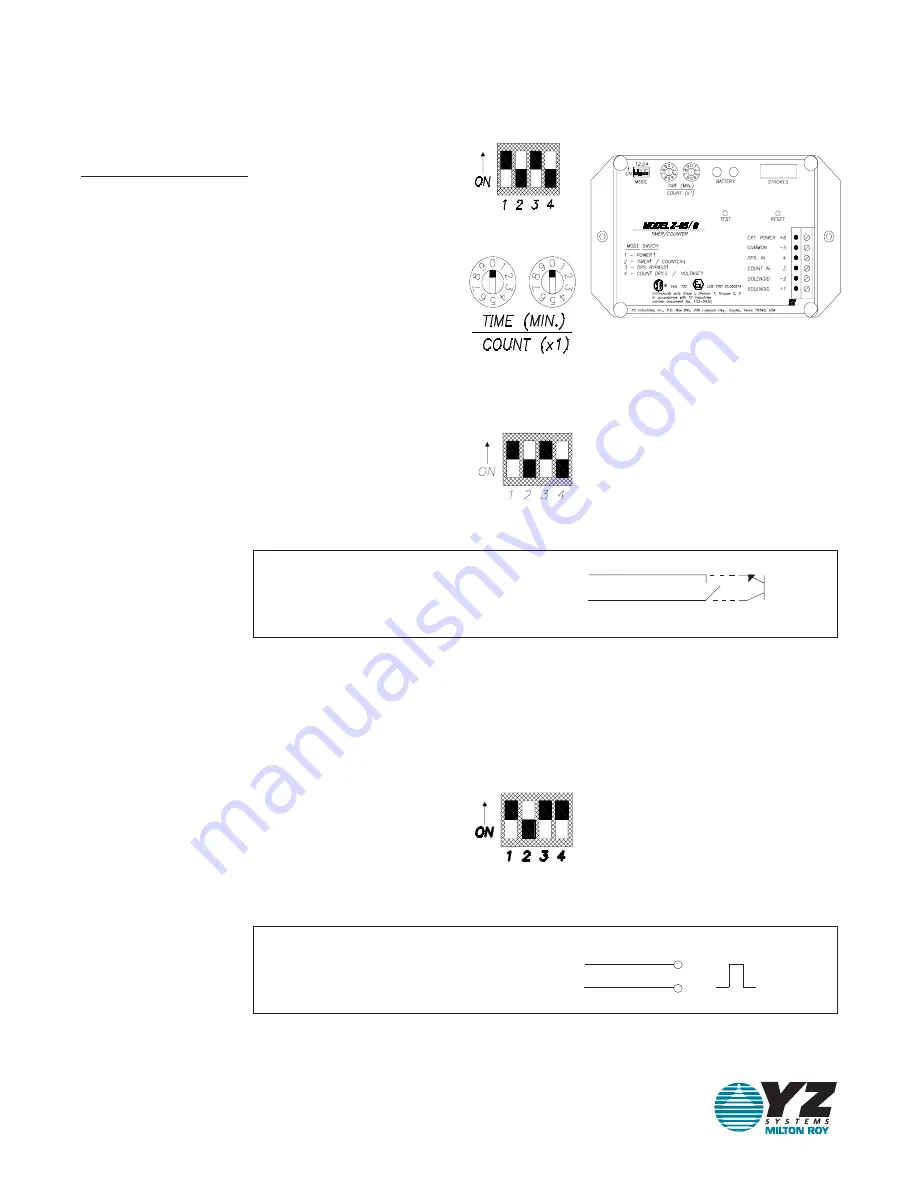
A. Set the mode switches as follows:
1. Position 1 and 3 on, 2 and 4 off.
B. Set the count switches to 00 to enter the
diagnostic mode. This mode enables the user to
determine if the proper input pulses are being
received at the count input (ter. #3).
1. Dry Contact Input: mode switch 4 should be in
the off position. Depress the test switch and hold.
A red LED should illuminate. When the dry
contact input is received at the counter input
(ter. #3) the green LED will turn on and off and the
red LED will illuminate again. This will normally
occur very quickly and give the appearance that
the green LED blinks on when the pulse input is
received and removed.
2. Voltage Pulse Input: move mode switch 4 to
the on position. Depress the test switch and hold.
A green LED should illuminate. When the voltage
pulse input is received at the count input (ter. #3)
the red LED will turn on and off and the green LED
will illuminate again. This will normally occur very
quickly and give the appearance that the red LED
blinks on when the pulse input is received and
removed.
dry contact
open collector
(20 mSec duration min.)
+
Ter. #5
Ter. #3
-
voltage pulse
-
+
Ter. #5
Ter. #3
5-24 VDC
(20 mSec duration min.)
Factory
System
Approved
Mutual
12. Trouble Shooting - Counter Mode


