YZ Systems Milton Roy • 201 Ivyland Road • Ivyland, Pennsylvania • USA • 18974 • P: 281.362.6500 • www.yzsystems.com
Page 5
NJEX EUR ver. 08-2021
Section 2: System Installation
Section 2: System Installation
Standard System Components
Standard primary components of the NJEX include
the following:
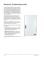
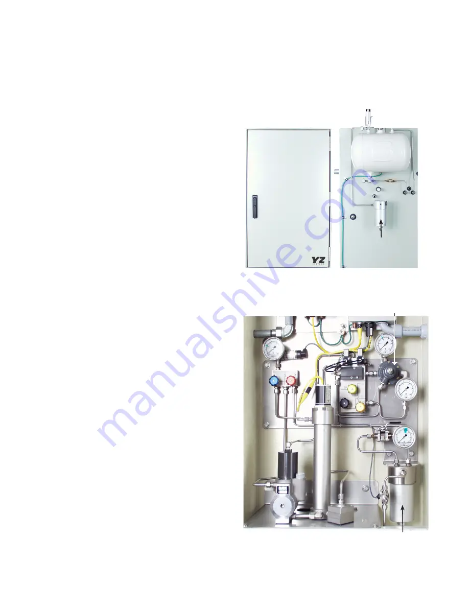
• System Enclosure, figure 1. Houses the pump, the
Verometer, the odorant fill valve, the solenoid valve/
pneumatic relay manifold, the odorant discharge
manifold, the system control enclosure.
• System Control Enclosure. Houses the N-300G
controller. (Not illustrated)
• Bulk Odorant Filter, figure 3. Provides primary
odorant filtration between the storage tank and the
NJEX. The Bulk Odorant Filter is pre-installed in-
side the System Enclosure attachment to the odor-
ant source is via an odorant inlet manifold equipped
with 1/4” FNPT connection located on the back of
the System Enclosure.
• Service Tray, (Not Illustrated), should be installed in
the bottom of the system enclosure, to capture any
drops that may occur during servicing of the odor-
izer.
• Mechanical Cabinet Cable, figure 3. Provides the
connection between the system control enclosure
and the electrical components in the mechanical
section.
• Expansion Tank, figure 2. Provides a closed loop
system for pressure fluctuations within the Verom-
eter during the odorant fill/injection cycle.
• NJEX Gas Filter, figure 2. Installed between the
actuation gas regulator and the actuation gas mani-
folds, this filter provides a 25 micron coalescent
filtration to insure a clean pneumatic supply.
• Actuation Gas Regulator, figure 3. Provides addi-
tional regulation of supply gas to actuate the pump.
Figure 2
Figure 3
System Enclosure
Figure 1
Expansion
Tank
NJEX Gas
Filter
Bulk Odorant Filter
Actuation Gas Regulator
Summary of Contents for NJEX 6300G
Page 1: ...NJEX 6300G 7300G N A T U R A L G A S O D O R I Z A T I O N S Y S T E M...
Page 2: ......
Page 3: ...NJEX 6300G 7300G Instruction Operating Manual Version 08 2021...
Page 4: ......
Page 10: ......


