YZ Systems Milton Roy • 201 Ivyland Road • Ivyland, Pennsylvania • USA • 18974 • P: 281.362.6500 • www.yzsystems.com
Page 40
NJEX EUR ver. 08-2021
Section 7: Calibrating Signal Inputs
Analog Flow Input Calibration,
1-5 VDC / 4-20 mA,
Continued
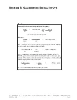
To calibrate the zero set point
,
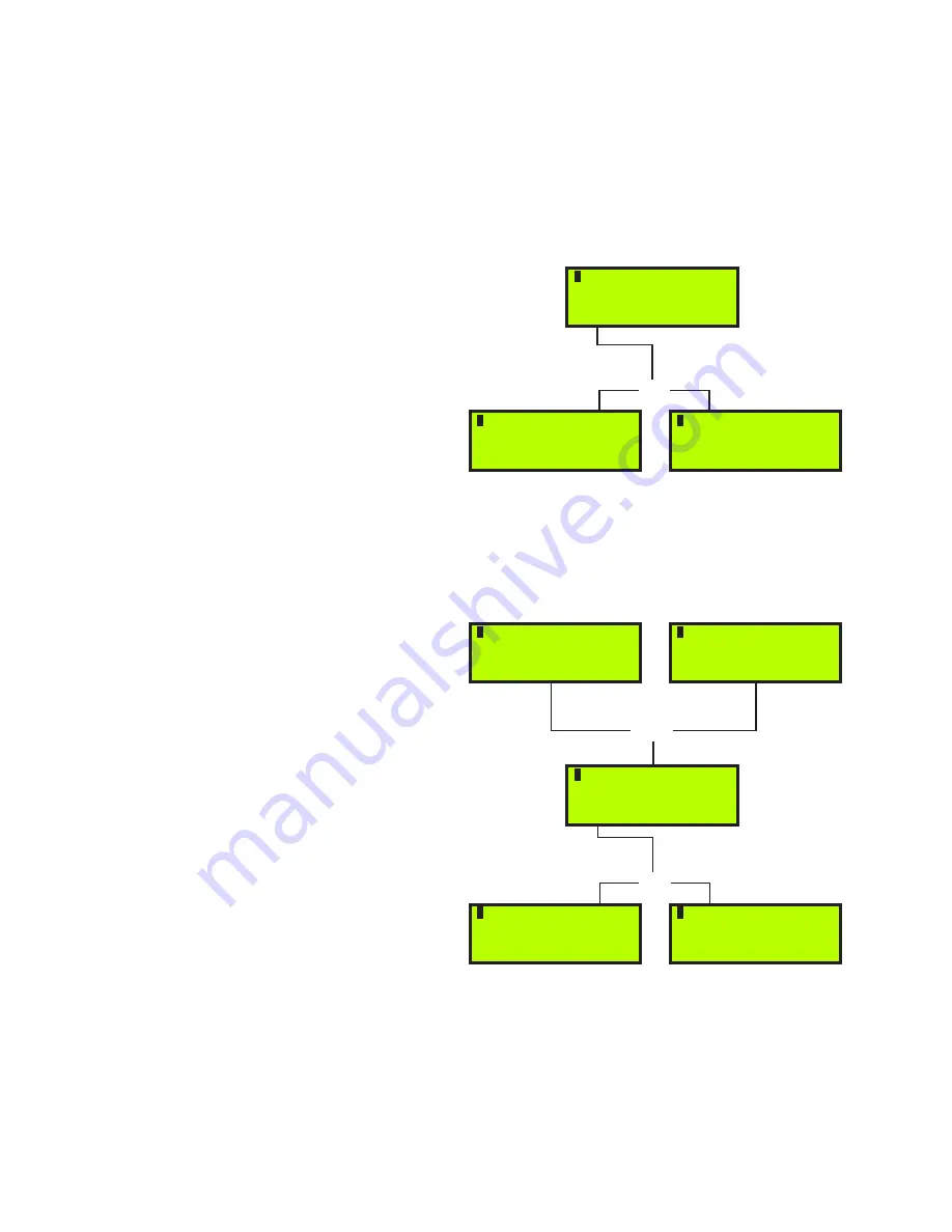
figure 81,
apply 1.00
VDC
(4.0 mA)
to the
TB1
terminal
#2
(+ positive sig-
nal input)
and terminal
#3
(- negative signal input)
. If
a Differential Pressure Transducer – DPT is used, out-
put from the transmitter should be 1.00 VDC
(4.0mA)
at 0 inches of water column differential
(0” w.c.)
.
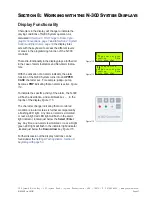
1. Press & release the
*Read
key and the voltage
present at the input terminals will be shown flash-
ing in the display.
2. Press & release the
*Accept
key to load the zero
point into the memory. This value will stop flash-
ing when this is completed,
figure 82
.
Note
: if an error message appears, figure 83, the
voltage at the input terminal is outside of the calibra-
tion range of .6V -1.4VDC (2.4 mA - 5.6 mA).
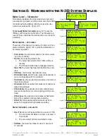
Choose Span to calibrate the full span set point
,
figure 84,
the span adjustment is used to calibrate
the N-300G controller for 100% of metered flow in the
pipeline. The N-300G is factory calibrated for 100%
of flow to directly correspond to 5.00 VDC
(20 mA)
at
the flow input terminal board
TB1
terminals
#2
and
#3
,
refer to the Wiring Control Document on page 117 in
.
To calibrate the span set point
, apply 5.00 VDC
(20
mA)
to
TB1
terminal
#2
(+ positive signal input)
and
terminal
#3
(- negative signal input)
. If a DPT is used,
output from the transmitter should be 5.00 VDC
(20
mA)
at maximum range of the meter, for example 5.00
VDC
(20 mA)
at 100 inches of water column differen-
tial
(100” w.c.)
.
1. Press & release the
*Read
key and the voltage
present at the input terminals will be shown flash-
ing in the display,
figure 85
.
2. Press & release the
*Accept
key to load the span
setting into the memory. This value will stop flash-
ing when this is completed,
figure 86
.
Note
: if an error message appears, figure 87, the
voltage at the input terminal is outside of the calibra-
tion range of 3.0V-5.5VDC (12 mA - 22 mA).
Or
Or
pmp bat vmtr sig tnk
Zero Adjustment
*Read 1.0V *Esc
pmp bat vmtr sig tnk
Zero Adjustment
*Accept *1.0v *Esc
pmp bat vmtr sig tnk
Zero Adjustment
ERROR 2.0v *Esc
Figure 81
pmp bat vmtr sig tnk
Linear Input
*Zero *Span *Esc
pmp bat vmtr sig tnk
Non Linear Input
*Zero *Span *Esc
pmp bat vmtr sig tnk
Span Adjustment
*Read 5.0V *Esc
Or
pmp bat vmtr sig tnk
Span Adjustment
*Accept 5.0V *Esc
pmp bat vmtr sig tnk
Span Adjustment
ERROR 2.0V *Esc
Figure 83
Figure 84
Figure 86
Figure 87
Figure 82
Figure 85
Summary of Contents for NJEX 6300G
Page 1: ...NJEX 6300G 7300G N A T U R A L G A S O D O R I Z A T I O N S Y S T E M...
Page 2: ......
Page 3: ...NJEX 6300G 7300G Instruction Operating Manual Version 08 2021...
Page 4: ......
Page 10: ......


