YZ Systems Milton Roy • 201 Ivyland Road • Ivyland, Pennsylvania • USA • 18974 • P: 281.362.6500 • www.yzsystems.com
Page 63
NJEX EUR ver. 08-2021
Section 10: Mechanical System
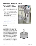
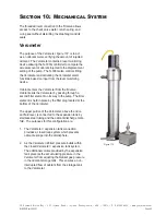
Figure 174
The threaded inlet connection to the fill valve allows
access to the check valve wafer, return spring, and
o-ring seal without disturbing the diaphragm and its
seals.
Verometer
The purpose of the Verometer,
figure 174
, is to act
as an odorant meter, verifying the amount of injected
odorant. The Verometer contains a level monitoring
device allowing the N-300G controller to compare the
actual amount of odorant injected to the displacement
setting of the pump. The N-300G also controls filling
the Verometer and activating the Verometer alarm
functions based on input from the level monitoring
device.
Odorant enters the Verometer from the fill valve.
Odorant exits the Verometer by passing through a
second filter element on its way to the pump. The filter
element is held in place by the filter plug located at the
bottom of the Verometer.
The upper portion of the Verometer, above the odor-
ant fluid level, is connected to the expansion tank by
stainless steel tubing and the odorant discharge mani-
fold. The purposes for this configuration are:
1. The Verometer / expansion tank connection
provides a closed loop system which prevents
odorant escape into the atmosphere.
2. As the Verometer is filled, pressure builds within
the closed Verometer / expansion tank system.
The additional volume provided by the expansion
tank prevents the accumulating pressure in the
Verometer from equaling the blanket gas pressure
in the odorant storage tank. This ensures an un-
interrupted flow of odorant from the storage tank
to the Verometer.
Summary of Contents for NJEX 6300G
Page 1: ...NJEX 6300G 7300G N A T U R A L G A S O D O R I Z A T I O N S Y S T E M...
Page 2: ......
Page 3: ...NJEX 6300G 7300G Instruction Operating Manual Version 08 2021...
Page 4: ......
Page 10: ......

