YZ Systems Milton Roy • 201 Ivyland Road • Ivyland, Pennsylvania • USA • 18974 • P: 281.362.6500 • www.yzsystems.com
Page 66
NJEX EUR ver. 08-2021
Section 10: Mechanical System
Solenoid Valve & Pneumatic
Relay Manifold
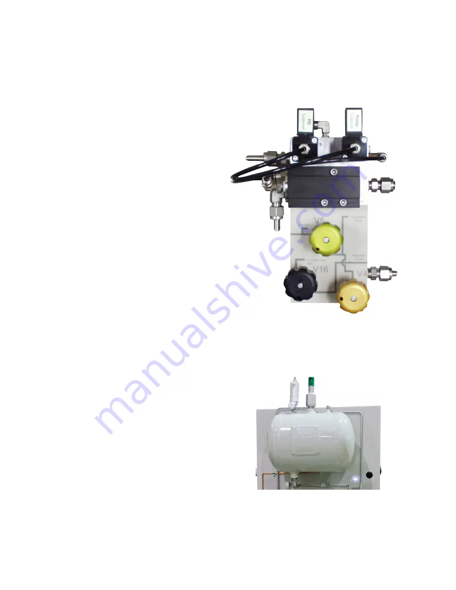
Two low power solenoid valves are mounted on this
manifold,
figure 178
. The solenoid valve,
SV2
located
on the left, actuates the fill valve, while the other sole-
noid valve,
SV1
located on the right, pilots the pump
pneumatic relay valve.
One pneumatic relay valve is also mounted on this
manifold. It is located just below the solenoid valves and
serves to actuate the pump when it receives a pneumat-
ic signal from the pilot relay discusses in the previous
paragraph.
Supply and exhaust ports are located on the outside
of the manifold to permit operator connections on the
back of the system enclosure.
Additionally, there are three control valves located
on this manifold,
V4
lower right with a gold knob,
V5
upper center with a green knob, and
V16
lower left
with a black knob. Valve
V4
is normally closed, but
is opened to charge the expansion tank with gas as
required during system start up or purge process.
Additionally, valve
V5
is normally closed, but is
opened to vent the gas from the expansion tank for
maintenance. Finally,
V16
is normally open, and is the
supply gas isolation valve.
Expansion Tank
The expansion tank,
figure 179,
is mounted on the
back of the enclosure and acts as a pressure source
and buffer for the Verometer. As the Verometer is
filled or emptied, blanket gas flows into or out of the
expansion tank as required. Because of the relatively
large difference in the volumes of the Verometer and
the expansion tank, the fluctuation in operating pres-
sure within this system is minimal.
Mounted on the expansion tank are: a relief valve, a
pressure gauge, a vent valve; and an expansion tank
isolation valve. The connection on the bottom of the
tank, valve
V14
, is used to connect the expansion
tank to the bypass loop.
Valve
V14
is normally closed, but can be opened as
an optional step in the forward purge process to purge
any liquid from the expansion tank that may have
accumulated, and place it back into the bulk storage
tank.
Figure 178
Figure 179
Expansion Tank
Summary of Contents for NJEX 6300G
Page 1: ...NJEX 6300G 7300G N A T U R A L G A S O D O R I Z A T I O N S Y S T E M...
Page 2: ......
Page 3: ...NJEX 6300G 7300G Instruction Operating Manual Version 08 2021...
Page 4: ......
Page 10: ......

