


YZ Systems Milton Roy • 201 Ivyland Road • Ivyland, Pennsylvania • USA • 18974 • P: 281.362.6500 • www.yzsystems.com
Page 8
NJEX 7300G ver.08-2018
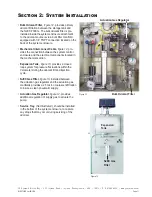
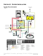
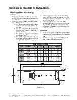
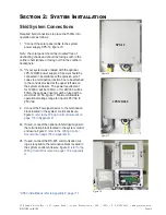
Section 2: System Installation
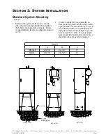
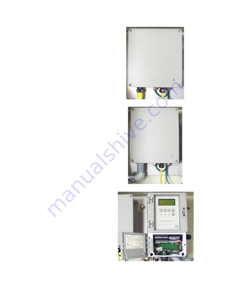
Figure 8
Figure 7
Figure 6
SPS-12
LPS120/240
* ATEX installations refer to Appendix E. page 117.
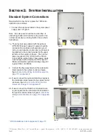
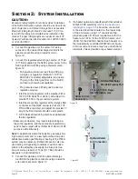
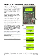
Standard System Connections
Required field connections to place the 7300G into
operation are as follows:
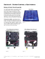
1. Connect the solar panel cable to the system power
supply, sps-12, figure 6.
Note: the solar panel should be mounted free of
obstructing shade and should be facing south in the
northern hemisphere or facing North in the southern
hemisphere.
1a. *If your system was ordered with the optional
LPS120/240 power supply, AC power should be
connected in accordance with explosion-proof
code via a termination junction box (not shown) to
be attached to the conduit provided at the upper
left side on the system enclosure. The nominal
power requirement for 120VAC will be 100 mA,
or for 240VAC will be 50mA. These power inputs
must be fused with a maximum of 15A, figure 7.
Minimum allowable operational voltage range for
input is 85VAC to 250VAC.
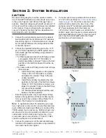
2. Connect the flow signal device to the termination
block located in the system control enclosure,
figure 8,
r
efer to the Wiring Control Document on
2a. If used, connect the optional Inhibit Input signal to
the termination block located in the system control
enclosure, figure 8,
Document on page 116 in Appendix D
.
2b. If used, connect the RS-485 communication wir-
ing as required to the termination block located in
the system control enclosure, figure 8,
Summary of Contents for NJEX 7300G
Page 1: ...NJEX 7300G N A T U R A L G A S O D O R I Z A T I O N S Y S T E M ...
Page 2: ......
Page 3: ...The NJEX 7300G Instruction Operating Manual Version 08 2018 ...
Page 4: ......
Page 10: ......


