YZ Systems Milton Roy • 201 Ivyland Road • Ivyland, Pennsylvania • USA • 18974 • P: 281.362.6500 • www.yzsystems.com
Page 64
NJEX 7300G ver. 08-2018
Section 10: Mechanical System
Model 7000F Pump
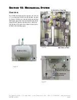
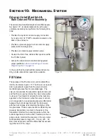
The NJEX 7000F pump,
figure 175,
is a pneumatically
actuated, positive displacement, reciprocating plunger
pump. The 7000F is actuated with compressed air or
pipeline gas at a pressure of 30 - 60 psi
(2.07 - 4.14
Bar)
refer to Section 2, the System Flow Schematic,
. The pump has an adjustable
displacement of 1.0cc, 0.8cc, 0.7cc, 0.6cc, 0.5cc,
0.4cc, 0.3cc or 0.2cc. It achieves proportional-to-
flow injection through adjustment of the stroke rate.
The 7000F is rated for a maximum stroke rate of 46
strokes per minute.
Each time the pump strokes, the plunger displaces
hydraulic fluid against the pump diaphragm, which in
turn displaces odorant through the discharge check
valve. The pump diaphragm acts as an isolation
device between the hydraulic fluid and the odorant,
minimizing the risk of odorant escape into the atmo-
sphere. Each time the plunger returns, it completely
removes itself from the plunger seal. This allows any
air trapped in the hydraulic system to be vented.
The 7000F incorporates a cartridge design in the four
areas that are most likely to require maintenance.
They are: the diaphragm assembly, the inlet check
valve, the discharge check valve, and the plunger
bushing / seal assembly. The cartridge design pro-
vides easier maintenance resulting in less down-time.
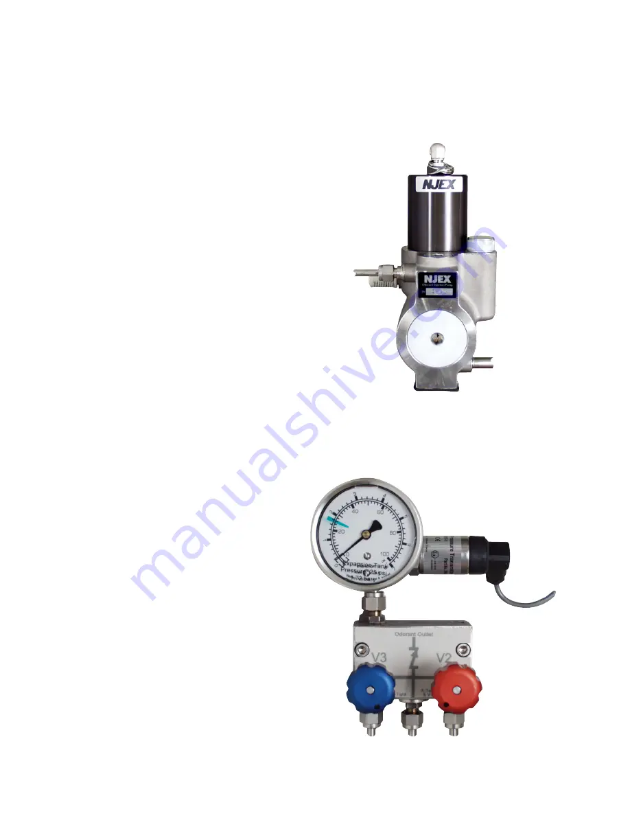
Odorant Discharge Manifold
This manifold is located on the back wall of the
mechanical enclosure, just to the left of the verom-
eter and above the pump,
figure 176
. This manifold,
located inside the enclosure, has three connections
on the bottom of the manifold. The inlet connection
in the center of the manifold is the pump discharge,
the connection to the right is to the Verometer and the
third connection to the left is to the purge bypass loop.
These fittings are connected at factory to the appropri-
ate component.
Three outlet ports for the odorant discharge manifold
are located on the back of the manifold and extend
through the enclosure wall. When facing the back of
Figure 176
Figure 175
Summary of Contents for NJEX 7300G
Page 1: ...NJEX 7300G N A T U R A L G A S O D O R I Z A T I O N S Y S T E M ...
Page 2: ......
Page 3: ...The NJEX 7300G Instruction Operating Manual Version 08 2018 ...
Page 4: ......
Page 10: ......

