background image


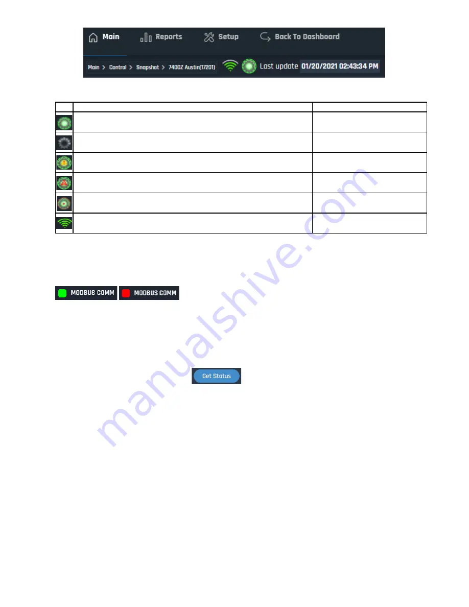
Icon Color and Signal Strength 


Check Modbus Communication 

On the Snapshot page for each odorizer is an LED indicator for Modbus communication.  If Modbus 
communication is functioning it will be GREEN, if it isn’t then it will be RED. 


If the Modbus Comm LED is RED, do the following: 

-


Check the Modbus wiring is correct at the controller and the YZ Connect Box. 

-


Check the Modbus settings on the controller match those listed at the beginning of this manual 

-


Ensure the correct Modbus port (COM1 or COM2) is enabled for the controller being used.  
Reference the NJEX or ZEO manual if necessary. 

-


After making any changes, click 

 to see if the indicator changes color 


Icon

Meaning

Action

Indicates the device is online and communicating with the servers

-

Indicates the device is offline and NOT communicating with the servers

Check power, call tech support for 
assistance if issue persists

Modbus Communication Error

Check Modbus wiring and settings on 
controller  

Unit has a Global Alarm

Select this unit and view the "Alarms" 
tab or the "Alarm Log"

Indicates there is a pending communication message with the device. 
The red outline may be there temporarily or constantly.

Check message in Download tab

Cellular service strength indicator

If you don't see any green bars call 
tech support for assistance

Summary of Contents for YZ Connect

Page 1: ...User Manual V1 0...

Page 2: ......

Page 3: ...s 7 YZ Connect Overview 5 Selecting an NJEX or ZEO Odorizer 5 Odorizer Management Overview 5 Functionality Overview 8 N 300 NJEX Snapshot 8 N 400 ZEO Snapshot 9 Alarms 9 Alarm Log 10 Event Log 10 Chan...

Page 4: ...higher users can control the odorizer and change parameters remotely USER level accounts only have the ability to remotely monitor equipment and cannot control or make parameter changes YZConnectLogi...

Page 5: ...ns SAFE AREA ONLY not approved for installation in Hazardous locations Installation Indoor Outdoor Enclosure NEMA 4X IP67 Ambient 4 to 140 F 20 to 60 C Electrical Single Phase 115 230VAC 0 55A 0 35A 5...

Page 6: ...reception when necessary To mount the antenna drill a hole 10 11mm 0 4 0 43 in diam and mount using the provided nut washer and foam sticker to maintain the IP rating Route the two antenna cables thro...

Page 7: ...y Voltage Single Phase 115 230VAC 50 60Hz Current 0 55A 0 35A 115 230V Required Wire Size 16AWG 1mm2 Wire Terminal Torque 4 4 lb in 5 kgf cm Wiring Overview Max RS 485 cable length between N 300 or N...

Page 8: ......

Page 9: ...s again OdorizerManagementOverview Main Reports and Setup are the three menu options on the top toolbar Select one to see drop down options From the mobile app select the to access the menu options fo...

Page 10: ...nit on a map so technicians or other employees can locate it o Hardware Parameters Configure a 4 20mA odorant sensor level sensor or other signal so it can be viewed and logged via YZ Connect o Suppor...

Page 11: ...eral Basic configuration of the device This will be configured by your company admin and should not need to be adjusted once set ID This number is the device ID When requesting support this number wil...

Page 12: ...erformance data for the NJEX odorizer on this page View pressures odorant level Verometer level serial totalizers stroke count and more USER level will see the User Snapshot which is the same as the b...

Page 13: ...ction rates pressures odorant level Verometer level pump performance totalizers flow signal serial and more USER level will see the User Snapshot which is the same as the below but without any of the...

Page 14: ...AlarmLog View the date and time when an alarm occurred and cleared Filter by date as necessary EventLog View key events and when they happened Filter by date as necessary...

Page 15: ...nges that were made to the unit It will highlight the most recent parameter change by default View the historical change log by changing the view to History Select two historical points to compare wha...

Page 16: ...opped in order to make changes In order to update parameters users must be ADMIN level or higher USER level cannot update parameters To update a parameter 1 Stop the odorizer 2 Adjust the parameter 3...

Page 17: ...This could be used to monitor a flow signal odorant sensor etc depending on the use case Setup 1 Add a hole for a NEMA 4X or IP67 rated cable gland in the YZ Connect box on the same side as the Anten...

Page 18: ...ilter parameters to graph via the drop down for Graphing Value View all the data individually or in a common graph Single view o When viewing all the data in a single view Click the parameter check bo...

Page 19: ...see the individual values at that time stamp Select the 3 bar icon in the upper right for download and print options Tabular YZ Connect data can be viewed in a table format for filtering and easy exp...

Page 20: ...ail and SMS Select users already setup in YZ Connect to get emails or text messages whenever a global alarm is triggered on the unit Each user can have two emails and a cell phone in their user settin...

Page 21: ...r to setup escalation 1 or 2 the user must have a cell phone number setup in YZ Connect Keeping an alarm from escalating When the user receives a text message they can respond with the code given in t...

Page 22: ...e the NJEX or ZEO manual if necessary After making any changes click to see if the indicator changes color Icon Meaning Action Indicates the device is online and communicating with the servers Indicat...

Page 23: ...wnload 5 Delete Message State 4 5 and 6 messages can be deleted 6 Flag the desired message from the details window and click delete 7 The icon should now be green again without the red border In the e...

Page 24: ...use 2 factor authentication to protect the logins of our users If it s the 1st time logging in on a device then YZ Connect will prompt the user for a code sent to the user logging in Why does my devic...

Page 25: ...www yz connect com Page 21 of 25 APPENDIX A Panel Control Drawing...

Reviews: