background image

ZPrinter

®

 310 Plus Hardware Manual

Quick Start Guide

zcentral.zcorp.com

13

All Rights Reserved

2/11/09

2.4 Useful Tips

2.4.1

Part Setup, Orientation and Print Settings

Do not tightly pack parts into the build. Keep in mind that you will need to depowder and remove 
them from the build box. Allow a little room around the part so you can vacuum the powder away 
and get your fingers around or under the part.

Orient parts so delicate features are supported in the Z-Axis. If a delicate feature is only supported 
by unprinted powder the chances of breaking that small feature during depowdering is greatly 
increased.

When building delicate parts always use a Fixture (see the 

ZPrint Software Manual

). Raise the part 

0.25" (6.4 mm) from the bottom of the build and generate a Fixture under the part. With a Fixture, 
the part can easily be handled, or transported to an oven or a depowder station.

Do not enable the 

Bleed Compensation

 if you are building a part with features under 0.050" (1.27 

mm). Go to 

zcentral.zcorp.com

or see the 

ZPrint Software Manual

 for additional information 

regarding this important feature. 

Parts printed with the High Performance Composite powders can be reliability printed to be within 
+/- 1.0% or +/- 0.005” dimensional tolerance.

To increase the strength of thin parts, you can decrease the layer thickness to 0.0035" (0.089 mm) 
if you are using one of the High Performance Composite materials. As you increase the strength of 
the part in this manner you are also increasing the amount of time to dry the part. Use of the 
removable build plate (see 

Section 2.4.3

) and oven drying the part are recommended. Remove the 

part from the removable build plate before placing in the oven.

2.4.2

Gross and Fine Depowdering

Use ZPrint to check where printed parts are located and oriented in the build box so you do not 
accidentally bump or brush against a fragile part when removing parts from the printer.

When removing powder from around the part, do not plunge the vacuum nozzle into the powder 
bed. Begin at the outer perimeter of the build box, slowly work your way into the build. Hold the tip 
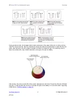
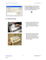
3.

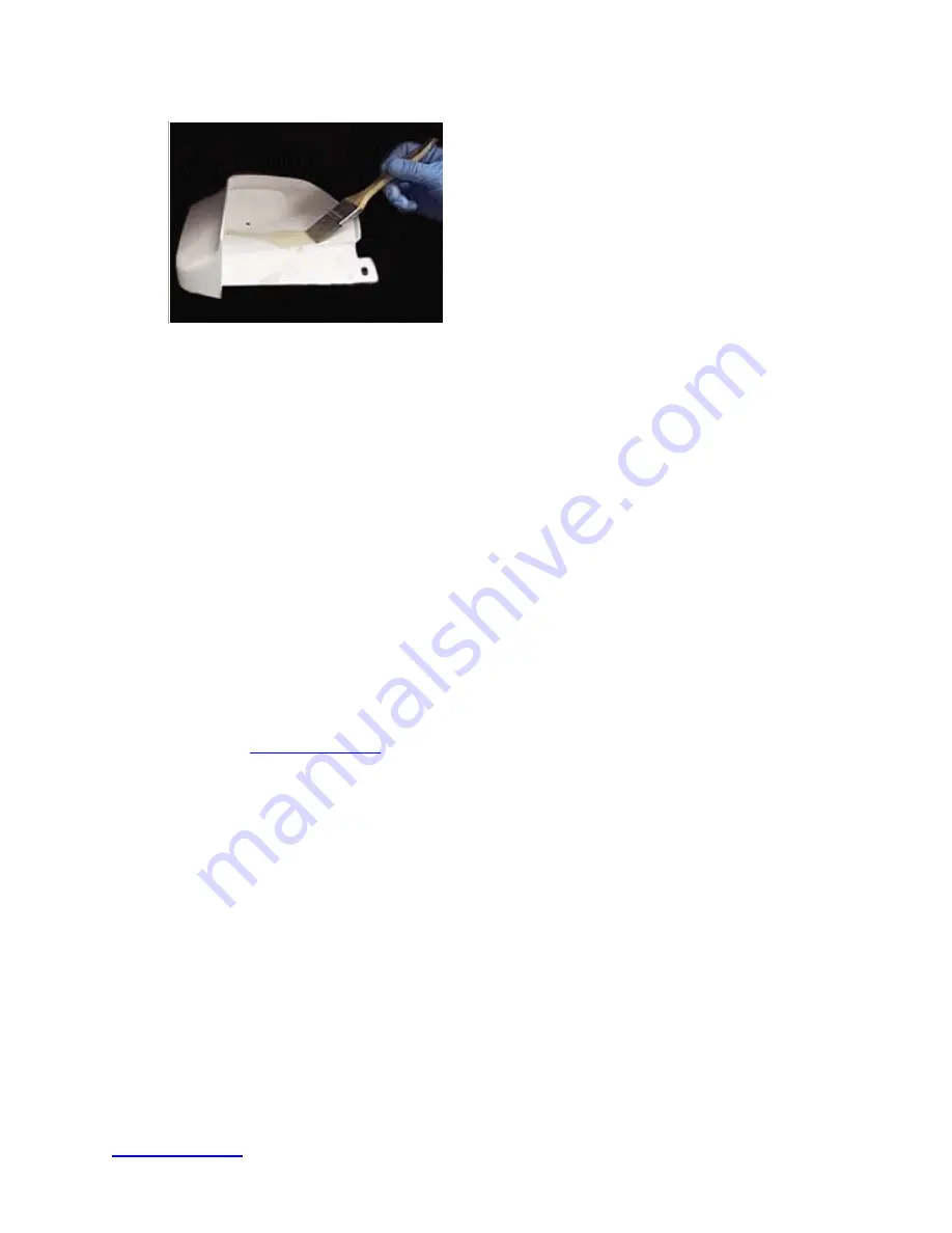
After the part is depowdered, you can 
allow it dry longer or you can infiltrate 
the part with the material of your 
choice. See 

Post-Processing

 for com-

plete information regarding different 
options for infiltration.

Summary of Contents for ZPRINTER 310 PLUS

Page 1: ...2002 2009 Z Corporation All Rights Reserved 2 11 09 ZPRINTER 310 PLUS HARDWARE MANUAL Part Number 09548 Rev D December 2008...

Page 2: ...Z Corporation Recipient shall not dis close such Information to any third party and shall not use it for any purpose whatsoever other than what is required to install and use the ZPrinter 310 Use of E...

Page 3: ...NESS FOR A PARTICULAR PURPOSE AND ANY OTHER OBLIGATIONS OR LIABILITIES WHETHER IN CONTRACT WARRANTY NEGLIGENCE OR OTHERWISE THE COMPANY IS NOT LIA BLE FOR ANY DIRECT INDIRECT SPECIAL PUNITIVE CONSEQUE...

Page 4: ...4 Prepare the 3D Printer 21 4 1 Start the Printer 21 4 2 Prepare the Build 21 4 2 1 Fill the Feed Box With Powder 21 4 2 2 Remove Air from the Powder and Pack the Feed Box 23 4 2 3 Prepare the Build...

Page 5: ...us 48 7 3 1 Temporarily Remove the Scraper Blade When Using ZCast 48 7 3 2 Load ZCast Powder 53 7 3 3 Spread Over The Build Bed and Print 53 7 3 4 Set Up ZCast Builds 53 7 3 5 Post Processing 53 7 3 6...

Page 6: ...9 8 12 Check Status 68 8 13 Print Head Report 68 8 14 View Printer Log 68 8 15 Upload New Firmware 69 8 16 Upload New Printer Configuration 69 8 17 Edit INI File Send File and Receive File 69 8 18 Mac...

Page 7: ...the bottom of the design to the top Inside the ZPrinter 310 Plus there are two pistons In the diagram below the feed piston is on the left and is shown in the down position filled with powder The bui...

Page 8: ...caffolding is created for the part walls which are also built with a higher saturation of binder for added strength The remaining interior areas are printed with a lower binder saturation which gives...

Page 9: ...parts once parts are infiltrated they uniformly take on the strength characteristics of the infiltrating material The ultimate strength of the part will be affected by its orientation within the buil...

Page 10: ...l Rights Reserved 2 11 09 1 2 System Components ZPrinter 310 Plus ZD5 Powder Recycling Station 1 3 ZPrinter 310 Plus Subcomponents Top Cover Binder Bottle on top of the Top Cover Service Station Gantr...

Page 11: ...ZPrinter 310 Plus Hardware Manual Overview zcentral zcorp com 5 All Rights Reserved 2 11 09 Back Panel View...

Page 12: ...ll Rights Reserved 2 11 09 1 4 Gantry Top View Gantry Top View Service Station Top View Squ eege e Sc rap er O il F ille r H oles C arriag e As s em bl y C arria ge Latc h C arria ge Plu nge r F as t...

Page 13: ...from left to right and allows you to spread powder over the build box Holding down this button will result in continuous spreading of powder Feed Up Feed Down Allows the user to raise or lower the pi...

Page 14: ...ZPrinter 310 Plus Hardware Manual Overview zcentral zcorp com 8 All Rights Reserved 2 11 09 ZD5 Powder Recycling Station...

Page 15: ...he Build In ZPrint on page 29 Post Processing on page 33 For additional information on post processing techniques visit the Z Corp 3DP User Web site at zcentral zcorp com 2 1 Printer Preparation 1 Fil...

Page 16: ...aper with a damp paper towel See Section 4 2 6 Steps 9 and 10 5 Check the binder level and fill if necessary Fill the binder fluid to the neck of the binder bottle See Section 4 2 7 6 Check the waste...

Page 17: ...her the printer is connected through either a Serial Port or Network connection The printer will show up as an option in the text field if the software is properly communicating with the printer 4 Che...

Page 18: ...the duration of the print Click OK to start the build 1 Get a tray for transporting the part and place it beside the build box Use the tools that ship with your printer to remove excess powder from th...

Page 19: ...onal information regarding this important feature Parts printed with the High Performance Composite powders can be reliability printed to be within 1 0 or 0 005 dimensional tolerance To increase the s...

Page 20: ...inted with one of the High Performance Composite materials can be handled when it is not completely dried the part reaches full strength when it is completely dried Placing the part in an oven at temp...

Reviews: