background image

ZPrinter

®

 310 Plus Hardware Manual

Quick Start Guide

zcentral.zcorp.com

14

All Rights Reserved

2/11/09

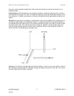
of vacuum nozzle approximately 0.25" (6.4 mm) to .375" (9.5 mm) away from the powder and 
allow the vacuum to pull the powder up. Slanting the vacuum nozzle will enable you to control the 
suction. This will decrease the chance of breaking a part during removal.

When fine depowdering, always start with low air pressure to minimize the chance of breaking fine 
details on the part. When the top and sides of the part are completely depowdered, tilt the part 
onto one of its sides. Handle the part carefully as it may be fragile and brittle before infiltration. If 
none of the sides of the part can support the weight of the part, you can apply a small amount of 
resin or epoxy to those areas to strengthen it. When doing this, be careful not to let any of the infil-
trant come into contact with any powder that may still be on the part. Let the infiltrant dry before 
continuing to depowder process.

2.4.3

Use of the Removable Build Plate

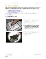
The removable build plate is an excellent tool. It allows you to quickly remove the part from the build 
bed, clean up the printer, and start printing again. The removable build plate also helps the user easily 
transport the part to an oven or a depowdering station without ever having to handle the part.

2.4.4

Oven Dry the Part

Although a part printed with one of the High Performance Composite materials can be handled when it 
is not completely dried, the part reaches full strength when it is completely dried. Placing the part in an 

oven at temperatures less than 200

o

F (93

o

C) for 2-4 hours will greatly increase the strength of the 

part. This is only recommended for parts printed with the High Performance Composite materials. 
Remove the part from the removable build plate before placing it in an oven.

2.4.5

Part Infiltration

Go to our ZCentral Web site at 

zcentral.zcorp.com

 for complete information on materials and applica-

tions.

When using Z-Bond™:

Always infiltrate the most delicate features of the part first. Z-Bond immediately strengthens the 
part areas it is applied to. Let the detailed areas cure for a couple of minutes and then continue 
applying Z-Bond to the remainder of the part. Do not apply Z-Bond to the same area twice.

Try to avoid infiltrating the part by applying Z-Bond from spot to spot. When drizzling Z-Bond onto 
a part, pick a good starting place and hold that area upward relative to the rest of the part. With 
your free hand, place the tip of the Z-Bond bottle against the part and allow the cyanoacrylate (CA) 
to flow from the bottle. It is important that the CA flows at a uniform rate and to see how quickly Z-
Bond wicks into the part. By seeing how quickly Z-Bond wicks into the part, it will be easier to 
judge where and how quickly to apply it. 

Keep the part moving in your hand when you apply Z-Bond. Doing this will prevent Z-Bond from 
sticking to your gloves. 

When Using Z-Max™ Epoxy:

Summary of Contents for ZPRINTER 310 PLUS

Page 1: ...2002 2009 Z Corporation All Rights Reserved 2 11 09 ZPRINTER 310 PLUS HARDWARE MANUAL Part Number 09548 Rev D December 2008...

Page 2: ...Z Corporation Recipient shall not dis close such Information to any third party and shall not use it for any purpose whatsoever other than what is required to install and use the ZPrinter 310 Use of E...

Page 3: ...NESS FOR A PARTICULAR PURPOSE AND ANY OTHER OBLIGATIONS OR LIABILITIES WHETHER IN CONTRACT WARRANTY NEGLIGENCE OR OTHERWISE THE COMPANY IS NOT LIA BLE FOR ANY DIRECT INDIRECT SPECIAL PUNITIVE CONSEQUE...

Page 4: ...4 Prepare the 3D Printer 21 4 1 Start the Printer 21 4 2 Prepare the Build 21 4 2 1 Fill the Feed Box With Powder 21 4 2 2 Remove Air from the Powder and Pack the Feed Box 23 4 2 3 Prepare the Build...

Page 5: ...us 48 7 3 1 Temporarily Remove the Scraper Blade When Using ZCast 48 7 3 2 Load ZCast Powder 53 7 3 3 Spread Over The Build Bed and Print 53 7 3 4 Set Up ZCast Builds 53 7 3 5 Post Processing 53 7 3 6...

Page 6: ...9 8 12 Check Status 68 8 13 Print Head Report 68 8 14 View Printer Log 68 8 15 Upload New Firmware 69 8 16 Upload New Printer Configuration 69 8 17 Edit INI File Send File and Receive File 69 8 18 Mac...

Page 7: ...the bottom of the design to the top Inside the ZPrinter 310 Plus there are two pistons In the diagram below the feed piston is on the left and is shown in the down position filled with powder The bui...

Page 8: ...caffolding is created for the part walls which are also built with a higher saturation of binder for added strength The remaining interior areas are printed with a lower binder saturation which gives...

Page 9: ...parts once parts are infiltrated they uniformly take on the strength characteristics of the infiltrating material The ultimate strength of the part will be affected by its orientation within the buil...

Page 10: ...l Rights Reserved 2 11 09 1 2 System Components ZPrinter 310 Plus ZD5 Powder Recycling Station 1 3 ZPrinter 310 Plus Subcomponents Top Cover Binder Bottle on top of the Top Cover Service Station Gantr...

Page 11: ...ZPrinter 310 Plus Hardware Manual Overview zcentral zcorp com 5 All Rights Reserved 2 11 09 Back Panel View...

Page 12: ...ll Rights Reserved 2 11 09 1 4 Gantry Top View Gantry Top View Service Station Top View Squ eege e Sc rap er O il F ille r H oles C arriag e As s em bl y C arria ge Latc h C arria ge Plu nge r F as t...

Page 13: ...from left to right and allows you to spread powder over the build box Holding down this button will result in continuous spreading of powder Feed Up Feed Down Allows the user to raise or lower the pi...

Page 14: ...ZPrinter 310 Plus Hardware Manual Overview zcentral zcorp com 8 All Rights Reserved 2 11 09 ZD5 Powder Recycling Station...

Page 15: ...he Build In ZPrint on page 29 Post Processing on page 33 For additional information on post processing techniques visit the Z Corp 3DP User Web site at zcentral zcorp com 2 1 Printer Preparation 1 Fil...

Page 16: ...aper with a damp paper towel See Section 4 2 6 Steps 9 and 10 5 Check the binder level and fill if necessary Fill the binder fluid to the neck of the binder bottle See Section 4 2 7 6 Check the waste...

Page 17: ...her the printer is connected through either a Serial Port or Network connection The printer will show up as an option in the text field if the software is properly communicating with the printer 4 Che...

Page 18: ...the duration of the print Click OK to start the build 1 Get a tray for transporting the part and place it beside the build box Use the tools that ship with your printer to remove excess powder from th...

Page 19: ...onal information regarding this important feature Parts printed with the High Performance Composite powders can be reliability printed to be within 1 0 or 0 005 dimensional tolerance To increase the s...

Page 20: ...inted with one of the High Performance Composite materials can be handled when it is not completely dried the part reaches full strength when it is completely dried Placing the part in an oven at temp...

Reviews: