Product
ZX
Date:
2018.09.19
Page:
18 of 62
Z-Laser Optoelektronik GmbH
Merzhauser Str. 134
D-79100 Freiburg
Tel.: (0761)29644-44
Fax: (0761)29644-55/56
Operation manual
Document-ID: UI-ZL-140011-0.9-2018-09-19
0.9
Author:
CSCH
Merzhauser Str. 134 ~ 79100 Freiburg ~ Tel.: +49-(0)761-29644-44 ~ Fax: +49-(0)761-29644-55
info@z-laser.de ~
www.z-laser.com
CAUTION NOTE
The analog modulation input (default Pin 4) has an internal pull-up
resistor. This leads to 100% of rated laser output power if the pin is
not driven by an external source. As a consequence the laser emits
with 100% of rated laser output power, if the analog modulation
input is directly connected to the digital modulation input.
CAUTION NOTE
Reducing the intensity via analog modulation (default Pin 4) does
not have an impact on the laser class.
Power supply
The ZX module can be supplied by 5…30 VDC (for 600…900nm modules) or 9…30 VDC (for 400…520nm
modules), respectively. The ZX will automatically transform the input into a proper internal voltage
level for the particular operating condition.
The supply input on Pin 1 is protected against reverse polarity and transient over voltages.
There is no ON-switch and shutter. Once supply voltage is applied, the module starts powering up.
During start-up procedure self-testing routines verify the safety architecture and integrity of the entire
system. After completion of these tests, laser emission starts by applying a TTL Trigger signal on Pin 2.
A simple way to permanently operate the module in Continuous Wave (CW) mode is to short-cut Pin 2
with the voltage supply (Pin 1).
System integrity tests are only conducted after power cycling the ZX laser module. To prevent
undetected accumulations of failures, the module should be power cycled on a regular base, e.g. once
every 24h. An integrated ON-time counter can be read out via TWI telegrams (see chapter 3.4.6) or
the GUI (see chapter 5) and indicates the time passed by since the last system integrity test.
Focus adjustment
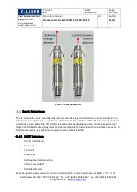
You can adjust the focus position of every focusable ZX module without any tools by turning the
knurling wheel. In order to prevent unintentional shift of focus, the rotation of the wheel is
mechanically impeded and you may need a bit of force to move it.
The focus position can be set to larger distance by turning the knurling wheel clockwise, by turning
the wheel counterclockwise you can focus the laser beam to shorter distance.


