Doc# 27-0017UM Issued 08/03 Rev 1.0
15
OPERATIONS
CABLE CONNECTIONS
TURN ON POWER
NOTE:
Connecting to non-
standard systems will
require an adapter.
To obtain a video
adapter, contact
Customer Services at
Z Microsystem, Inc.
NOTE:
Incorrect cable
connections may
result in irregular
operation. Incorrect
cable connections
may also damage the
display quality or
components of the
LCD module, and may
shorten the life of the
unit. Always consult
the computer system
manual. Verify the
system’s compatibility
to ensure proper
operation.
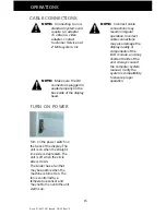
Turn on the power switch on
the back of the display. The
unit is on when the straight
line side is depressed. The
unit is off when the circle
side is down.
The Glider has a fan that
may be audible when the
machine is turned on. The
fan is controlled by a
temperature sensor and
may not turn on until the unit
warms up.
NOTE:
Make sure the DC
connector is plugged in
seated properly on the
back side of the display
head.
Summary of Contents for Glider 21
Page 1: ...Glider 21 FIELD READY User Manual Z Microsystems ...
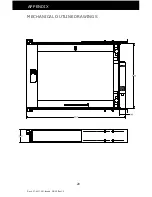
Page 29: ...Doc 27 0017UM Issued 08 03 Rev 1 0 29 APPENDIX MECHANICAL OUTLINE DRAWINGS ...
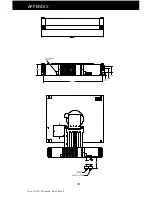
Page 30: ...Doc 27 0017UM Issued 08 03 Rev 1 0 30 APPENDIX ...
Page 31: ...Doc 27 0017UM Issued 08 03 Rev 1 0 31 APPENDIX ...
Page 32: ...Doc 27 0017UM Issued 08 03 Rev 1 0 32 APPENDIX ...
Page 33: ...Doc 27 0017UM Issued 08 03 Rev 1 0 33 APPENDIX ...


