Doc# 27-0017UM Issued 08/03 Rev 1.0
17
OPERATIONS
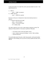
The three LED lights on the right of the control panel are labeled A, B and C. Their
lighted functions are:
A — VIDEO A
green — VIDEO A is selected
B — VIDEO B (green)
green — VIDEO B is selected
If A & B are both green, it indicates the Channel Auto Switching function is
selected.
C — Computer Graphics (green/orange)
green — power and signal
orange — power and no signal
off — Standby mode
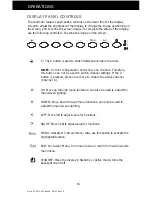
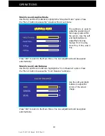
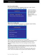
This section explains how to use the control buttons to adjust the clarity of the
display and image position on the screen. In particular it discusses:
• The function of each of the push-button controls
• How to reset previously saved settings or return to factory settings
• Tips and techniques
The control buttons allow the user to control image position, clarity and backlight
operations; to store settings, and to revert to previously operations factory-saved
settings.
Summary of Contents for Glider 21
Page 1: ...Glider 21 FIELD READY User Manual Z Microsystems ...
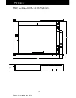
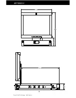
Page 29: ...Doc 27 0017UM Issued 08 03 Rev 1 0 29 APPENDIX MECHANICAL OUTLINE DRAWINGS ...
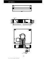
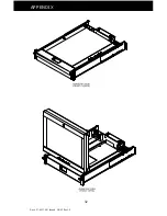
Page 30: ...Doc 27 0017UM Issued 08 03 Rev 1 0 30 APPENDIX ...
Page 31: ...Doc 27 0017UM Issued 08 03 Rev 1 0 31 APPENDIX ...
Page 32: ...Doc 27 0017UM Issued 08 03 Rev 1 0 32 APPENDIX ...
Page 33: ...Doc 27 0017UM Issued 08 03 Rev 1 0 33 APPENDIX ...

