background image

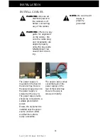
Doc# 27-0017UM  Issued  08/03 Rev 1.0

25

TROUBLESHOOTING

NO IMAGE ON MAIN DISPLAY

If there is no image on the main screen, a signal will appear on the screen that
states, “No Input, Check Cable”. If the cable from the computer to the display is
secure, determine the color of the standby LED and follow the appropriate
procedure below.

B

LACK

Cause: If the standby LED is black, there is no power to the unit.
Recovery:

•  Ensure the power cable is plugged into the source.
•  Connect the power cable to  the AC outlet. Ensure the
AC outlet is active.
•  Wake up the display by pressing the standby button.

O

RANGE

Cause: If the standby LED is orange, there is no video signal.
Recovery:

•  Ensure there is a video signal coming from the computer.
•  If no image appears, press the Z button on the control panel.

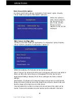
•  If this fails to activate the image, use the on-screen menu. Within

the Configuration menu is the “Channel Select” option. Switch
between A and B to activate the proper channel.

G

REEN

Cause: When the standby LED is green, there is both power and a video
signal. If there is no image on the main display, there is a possible hardware
failure.
Recovery:

•  Ensure the video signal coming from the computer is
not a black screen.
•  Contact Z Microsystems’ Customer Support Department.

Summary of Contents for Glider 21

Page 1: ...Glider 21 FIELD READY User Manual Z Microsystems ...

Page 2: ... These limits are designed to provide reasonable protection against harmful interference in when equipment is operated in commercial environments This equipment generates uses and can radiate radio frequency energy and if not installed and used in accordance with the instruction manual may cause harmful interference to radio communications 3 Operation of this equipment in a residential area is lik...

Page 3: ... Slides In Cabinet Frame 8 Installation Test 10 Final Adjustments 10 Install Cables 11 SETUP 12 Setting Up Glider 12 PROTECTOR REMOVAL 14 OPERATIONS 15 Cable Connections 15 Turn On Power 15 Display Panel Controls 16 Menus 18 DISPLAY HEAD REMOVAL 21 MAINTENANCE 22 DISPLAY STOWAGE 23 Close Glider 23 TROUBLESHOOTING 25 No Image on Main Display 25 SPECIFICATIONS 26 APPENDIX 27 Support 27 Replacing Par...

Page 4: ...ided for quickly finding technical information about the Glider FEATURES Large Display Area Wide Viewing Angle Small Package Outline Full Color High Contrast Ratio The Glider works with any computer system that provides industry standard screen formats from 640 x 480 to 1600 x 1200 with up to 75 Hz vertical sync The Glider shipping box contains the following The Glider Unit Host Serial Cable AC Po...

Page 5: ...ace in standard 19 racks and transit cases The Glider can be oriented for a portrait format The lightweight and durable aluminum construction provides exceptional strength in field applications The high quality LCD screen provides full color and features up to 1600 x 1200 pixel resolution The side viewing angle is up to 160 degrees The monitor can be adjusted to multi viewing positions and oriente...

Page 6: ...on the display front will not be illumi nated and the power switch will be down toward the circle WARNING To avoid shock hazard Do not remove the covers around the Glider Do not connect or disconnect the Glider during an electrical storm The power cord plug must be connected to a properly wired and grounded power outlet Any equipment to which the Glider will be attached must also be connected to p...

Page 7: ...the Glider to slide the side rails back The slide rails will reach a stop about half way back This is a safety stop to prevent the Glider from sliding out too far while mounted in the rack Simultaneously press in the safety catches on each slide rail and slide the side rails all the way off the back of the Glider The slides should now be separated from the Glider ...

Page 8: ...illips screws to loosely secure the right and left rear slide mounts to the cabinet frame DO NOT tighten these screws fully On the front of the cabinet frame use three Phillips screws and washers per side to secure the right and left Z Lock mounts holding the sliders DO NOT tighten these screws to allow for adjustment of the Glider within the cabinet frame As seen from this reverse view align the ...

Page 9: ...r MUST be level This step may best be done with two people one on each side of the slide rails If the Glider binds during insertion the Glider rollers are not properly aligned into the slider recepticle Simultaneously press in the catches on each slider and move the Glider all the way into the cabinet frame Feed the cables from the Glider back through the cabinet frame Guide the Glider into the sl...

Page 10: ...e back of the cabinet the Glider may need to be removed to tighten the rail screws The Glider should now slide in and out smoothly If not repeat these steps Because of variances in cabinet frames there may need to be some adjustments of the Glider slide system for best fit and movement of the Glider in and out If the Glider binds when rolling in and out perform the following procedures Slide the G...

Page 11: ...t ing INSTALL CABLES The power cable comes out at the back of the power supply on the rear of the Glider tray Be sure the plug is screwed in tightly The power supply is mounted on the back of the Glider tray Be sure the power plug going in to the power supply is screwed all the way in The power supply cable should be connected to a suitable grounded AC power Ensure the equipment is installed near ...

Page 12: ...ft the back of the pivioted display up to the vertical position With both hands press both the Z Locks down SETTING UP GLIDER Slide the Glider all the way out to the safety stop Once the display is locked in position lower the latch back into the base recepticle If your unit is equipped with lock down features lift and slide the two display lock knobs at the back of the display to the open or inwa...

Page 13: ... angled positions The display can also be moved into the horizon tal position The control knobs will be on the bottom The display can be left in the vertical position or tilted back SETTING UP GLIDER The Glider can be slid back until the back of the display almost touches the cabinet ...

Page 14: ...ile the display is in operation To remove the display protector do the following Rotate the display to the horizontal position with the controls on the bottom Move the display protector release button located above the display up While holding up the display protector button slide the protector to the right Slide the protector off the edge of the display To reinstall the display protector during l...

Page 15: ...the LCD module and may shorten the life of the unit Always consult the computer system manual Verify the system s compatibility to ensure proper operation Turn on the power switch on the back of the display The unit is on when the straight line side is depressed The unit is off when the circle side is down The Glider has a fan that may be audible when the machine is turned on The fan is controlled...

Page 16: ...ly one channel Therefore this button can not be used to switch channel settings If the Z button is pressed press once more to enable the active channel Channel A UP Move up through menu functions can also be used to adjust the main screen lighting DOWN Move down through menu functions can also be used to adjust the main screen lighting LEFT Move left to adjust value for functions RIGHT Move right ...

Page 17: ...een orange green power and signal orange power and no signal off Standby mode This section explains how to use the control buttons to adjust the clarity of the display and image position on the screen In particular it discusses The function of each of the push button controls How to reset previously saved settings or return to factory settings Tips and techniques The control buttons allow the user...

Page 18: ... for specifics regarding the submenus Main Screen Picture Adjust Use the Up and Down buttons to highlight the Picture Adjust option Press the Menu button to access the submenu NOTE Brightness of the main screen can also be adjusted without entering the Main Menu using the up and down display buttons Use the Left and Right buttons to increase and decrease the Brightness and Contrast character istic...

Page 19: ...light the Graphics Mode option Press the Menu button to access the Graphics Mode submenu Press Exit to return to the Main Menu The new adjustments will be applied automatically Main Screen Color Balance Use the Up and Down buttons to highlight the Color Balance option Press the Menu button to access the Color Balance submenu Use the Left and Right buttons to adjust the colors of the screen image P...

Page 20: ...n submenu Within this submenu the following items can be accessed Menu Timeout The amount of time the menu will appear while not in use before it times out When the menu times out it disappears from the main screen Reset Default Settings Resets all Main Menu settings to the factory default settings Auto Position This feature will center the image on the screen In order for this feature to function...

Page 21: ...o the horizontal position On the back of the display disconnect the power cable Disconnect the video cable Swing the display locking bar out Use two hands to lift the display up out of the rack mount Be careful that the power and video cables do not catch on anything The display is now removed from the head mount WARNING Be sure all electrical power is turned off to the Glider before proceeding Di...

Page 22: ...d mild detergent or alcohol DO NOT use solvents or abrasives Never use flammable cleaning material to clean the monitor or other ectrical apparatus WARNING To avoid risk of electric shock DO NOT dissemble the monitor cabinet User maintenance is restricted to cleaning as explained here WARNING Be sure to turn off the power before performing any maintenance on the monitor ...

Page 23: ...back towards the rear of the rack all the way to the horizontal position in order to Rotate the display locking latch counter clockwise to release the side lock linkage VER VER VER VER VERY IMPORT Y IMPORT Y IMPORT Y IMPORT Y IMPORTANT ANT ANT ANT ANT Hold the top of the display while rotating the locking latch Make sure there is enough room to lower the top of the display head without hitting the...

Page 24: ...into its recepticle CLOSE GLIDER Slide the Glider into the frame until the Z Locks snap into the closed secure position Slide the two display locking bolts at the back of the display to the closed position to secure the display The display latch has now locked the side linkage ...

Page 25: ...t is active Wake up the display by pressing the standby button ORANGE Cause If the standby LED is orange there is no video signal Recovery Ensure there is a video signal coming from the computer If no image appears press the Z button on the control panel If this fails to activate the image use the on screen menu Within the Configuration menu is the Channel Select option Switch between A and B to a...

Page 26: ... to 40C Extended Operating Temp 20 to 50C Non Op Temp 40 to 70C Operating Humidity 5 95 Non Condensing Non Op Humidity 5 95 Non Condensing Operating Altitude 1 300 to 15 000 ft Non Op Altitude 1 300 to 40 000 ft Vibration MIL STD 167 Shock MIL STD 810E 20 g s MIL STD 901D in isolated rack Sand and Dust 5 5 MPH for 25 min display head only Drip Proof MIL STD 810E display head only Fungus Non Nutrie...

Page 27: ...w zmicro com If you are unable to correct any problem yourself contact Z Microsystems at 858 657 1000 Fax 858 657 1001 Website www zmicro com Before calling please have available as much of the following information as possible 1 Model and serial number from the label on the monitor 2 Purchase Order number 3 Description of problem 4 Computer type and model 5 System configuration hardware fitted et...

Page 28: ...rmation is required when returning Z Microsystems products 1 Model number 2 Serial number 3 Date of purchase 4 Proof of purchase use the invoice or packing slip 5 Customer ship to address and any special shipping requirements 6 Specific and detailed description of the problem PROVIDING FEEDBACK We value your feedback on our products and their performance and always welcome constructive sugges tion...

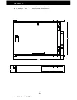
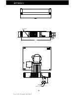
Page 29: ...Doc 27 0017UM Issued 08 03 Rev 1 0 29 APPENDIX MECHANICAL OUTLINE DRAWINGS ...

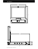
Page 30: ...Doc 27 0017UM Issued 08 03 Rev 1 0 30 APPENDIX ...

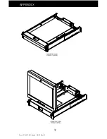
Page 31: ...Doc 27 0017UM Issued 08 03 Rev 1 0 31 APPENDIX ...

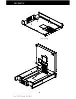
Page 32: ...Doc 27 0017UM Issued 08 03 Rev 1 0 32 APPENDIX ...

Page 33: ...Doc 27 0017UM Issued 08 03 Rev 1 0 33 APPENDIX ...

Page 34: ...Z Microsystems Inc 5945 Pacific Center Blvd Suite 505 San Diego CA 92121 Phone 858 657 1000 Fax 858 657 1001 Website www zmicro com Copyright 1999 Z Microsystems Inc All Rights Reserved ...

Reviews: