background image

Doc# 27-0030UM Rev 1.0 Issued  12/04

45

APPENDIX

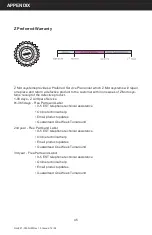
Z Microsystems provides a Preferred Service Plan under which Z Microsystems will repair 
or replace and return a defective product to the customer within one week of Z Microsys-
tems’ receipt of the defective product. 
1-90 days - Z AirSpare Service
91-365 days - Free Parts and Labor

  •  9-5 EST telephone technical assistance

  •  Online technical help

  •  Email product updates

  •  Guaranteed One Week Turnaround

2nd year - Free Parts and Labor 

  •  9-5 EST telephone technical assistance

  •  Online technical help

  •  Email product updates

  •  Guaranteed One Week Turnaround 

3rd year - Free Parts and Labor 

  •  9-5 EST telephone technical assistance

  •  Online technical help

  •  Email product updates 

  •  Guaranteed One Week Turnaround  

Z Preferred Warranty


Summary of Contents for TranzStor 8X

Page 1: ...User Manual T ranzStor 8X Z Microsystems FIELD READY...

Page 2: ...ON CORD RECEPTACLE OR OTHER OUTLETS UNLESS ALL THREE PRONGS CAN BE FULLY INSERTED CAUTION RISK OF ELECTRIC SHOCK DO NOT OPEN CAUTION TO REDUCE THE RISK OF ELECTRIC SHOCK DO NOT REMOVE COVER OR BACK OF...

Page 3: ...blish Serial Connection 13 Verify Channel Settings 14 Begin Quick Install Wizard 15 Add New Logical Drive 17 Status Indicators 20 TP7 Description 21 Inserting the TP7 22 Removing the TP7 23 Removing t...

Page 4: ...ower cord plug must be connected to a properly wired and grounded power outlet Any equipment to which the 8X will be attached must also be connected to properly wired and grounded power outlets This M...

Page 5: ...performance and fault tolerance they require Packed in a tough lightweight compact aluminum enclosure this fail proof hot plug stor age installs easily into any industry standard 7 4U RETMA rack or tr...

Page 6: ...l Shipment Contents 8X Raid Enclosure Power Sup plies and TP7s installed 6 Screw SEM Phillips 10 32 x 1 00 SS 01 92220 4 Screw Pkh Phillips 10 32 x 0 375Lng SS 01 92087 16 Washer 10 Flat SS 01 91872 a...

Page 7: ...j k l m n o p Raid Controller Manual Warranty Service Plan 8X User Manual Electronic Documentation l Null Modem Cable DB9F to DB9F IEC Power Cable Rack Slides SCSI LVD SE External Terminators Quantit...

Page 8: ...8X follow these steps in the sequence they are presented PREPARATIONS In preparation to install the 8X take the following precautionary steps Turn off the electrical power to the host computer INSTAL...

Page 9: ...ecure loosely with at and lock washers Do not tighten Repeat with the second slide assembly Positioning the slide assembly on the inside of the rack secure the front of the slide assembly to the front...

Page 10: ...locking tab on the outer sides of the slides and remove the inner members of the slide assemblies Lay the inner members along either side of the 8X RAID placing the pointed end of the members toward t...

Page 11: ...aching the inner members of the slide assemblies to the sides of the 8X RAID ensure screw penetration does not exceed 3 16 length Damage may result if screw length exceeds 3 16 length Use 10 32 x 3 16...

Page 12: ...ese cables TranzStor 8X con gurations may vary 1 Terminate external SCSI connectors 2 Connect SCSI Adapter to Host Computer s SCSI adapter using a 68 pin external SCSI cable 3 Connect Serial CTRL A to...

Page 13: ...arity None Stop bits 1 Flow control None Before powering the TranzStor 8X make sure all of the connections are tightened se curely at the rear of the unit STEP 4 POWER UP TRANZSTOR 8X Power Switch Fro...

Page 14: ...nu select PC Graphic ANSI Mode and press Enter This will take you to the Main Menu Verify that your channel settings match the image below If your channel settings do NOT match you can not continue wi...

Page 15: ...eate logical drive Initialization will begin and will continue for up to two hours depending on the drive ca pacity about 2 hours for a 146 GB drive STEP 7 BEGIN QUICK INSTALL WIZARD Select top option...

Page 16: ...0030UM Rev 1 0 Issued 12 04 16 OPERATIONS Press the ESC key Once the initialization is complete the progress counter will disappear Select System Functions then Reset the Controller and nally Yes to...

Page 17: ...ost computer by right clicking on the SCSI controller in the device manager Go to Administrative Tools Computer Management Disk Management Click on Disk Management to start up Write Signature and Upgr...

Page 18: ...tart up the Create Volume Wizard automatically If the Wizard doesn t start up automaically right click on unallocated disk and select create volume OPERATIONS NOTE If the Disk symbol is shown as unall...

Page 19: ...Doc 27 0030UM Rev 1 0 Issued 12 04 19 Once complete the new drive can be found in the same le location as the rst available drive under My Computer OPERATIONS...

Page 20: ...wer Activity The System Power Indicator illuminates when power to the system is detected The Drive Status Indicator illuminates when a drive is active The Alert Indicator illuminates when the system d...

Page 21: ...Drive Rear Connector High tensile extruded aluminium alloy thermo conductive body High tensile diecast alu minium alloy rear panel High tensile diecast alu minium alloy front panel TP7 DESCRIPTION Sl...

Page 22: ...is sliding on the black guides Using your thumb push the TranzPak 7 gently into the bay until you can feel it touching off on the rear connector Check that the locking catch is aligned with the lockin...

Page 23: ...dle springs open Pull handle gently forward to eject the TranzPak 7 off of the rear connector Continue to gently pull handle to slide the TranzPak 7 forward The TranzPak 7 should slide over the ground...

Page 24: ...come loose The door can be removed by lifting it down and off of the hinge To remove the controller door turn the thumbscrews on the face of the door counterclockwise NOTE For information regarding r...

Page 25: ...the bottom of the door down to align the thumbscrews with the screw holes To install the controller door seat the hinges up into the hinge slots at a 45 degree angle Simultaneously press and turn the...

Page 26: ...you perform any maintenance on the RAID CLEANING THE TRANZSTOR 8X Unplug the 8X from the power outlet before cleaning To clean the surface of the 8X lightly dampen a soft clean cloth with water or mil...

Page 27: ...anz Stor 8X chassis Rotate the fan assembly upward on the hinge and then down To install the new fan assembly place the two hinges into the hinge slots shown in the next photo at a 45 degree angle The...

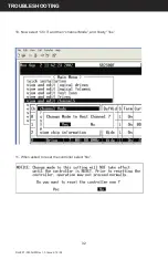
Page 28: ...to factory default settings follow these steps to recover TROUBLESHOOTING 2 Now select Chl 0 and then channel Mode and then select Yes TROUBLESHOOTING 1 Select view and edit channels NOTE Optimal setu...

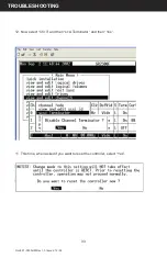
Page 29: ...29 3 At this point you will be asked if you want to reset the controller Select No 4 Now select Chl 1 and then Channel Mode and then Yes TROUBLESHOOTING 5 At this point you will be asked if you want...

Page 30: ...Doc 27 0030UM Rev 1 0 Issued 12 04 30 7 When asked to reset the controller select No 6 Now select Chl 2 and then Channel Mode and then Yes TROUBLESHOOTING...

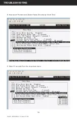
Page 31: ...Doc 27 0030UM Rev 1 0 Issued 12 04 31 8 Now select Chl 2 and then scsi Terminator and then Yes TROUBLESHOOTING 9 When asked to reset the controller select No...

Page 32: ...Doc 27 0030UM Rev 1 0 Issued 12 04 32 10 Now select Chl 3 and then channel Mode and nally Yes TROUBLESHOOTING 11 When asked to reset the controller select No...

Page 33: ...Doc 27 0030UM Rev 1 0 Issued 12 04 33 12 Now select Chl 3 and then scsi Terminator and then Yes TROUBLESHOOTING 11 This time when asked if you want to reset the controller select Yes...

Page 34: ...hat the drives show activity 2 Ensure the drives are seated securely in the 8X Remove the failed drive and re install it to ensure a good connection 3 Ensure that the power indicators on the front of...

Page 35: ...B Now select Auto Assign Global Spare Drive When asked Enable Auto Assign Global Spare select Yes C Finally select Drive Predictable Failure Mode SMART and then Detect Only When asked Set Drive SMART...

Page 36: ...Doc 27 0030UM Rev 1 0 Issued 12 04 36 D Now select Periodic Auto Detect Failure Drive Swap Check Time E Select 5 seconds from the drop down menu TROUBLESHOOTING...

Page 37: ...0 Issued 12 04 37 F When asked Set Periodic Auto Detect Failure Drive Swap Check Time select Yes G Press Esc once to return to the previous menu H Now select Controller Parameters followed by SDRAM E...

Page 38: ...ng after attempting these troubleshooting steps call the Z Microsys tems Customer Service Department for further assistance I When asked Enable SDRAM ECC Functionality select Yes J When asked Do you w...

Page 39: ...04 39 MECHANICAL OUTLINE FOR 8X WARNING There is a maximum of 18 screw penetration on the underside and side screw hole locations Only use screws provided Use of longer screws may result in damage to...

Page 40: ...Doc 27 0030UM Rev 1 0 Issued 12 04 40 MECHANICAL OUTLINE FOR 8X SCHEMATICS 17 64 18 69 18 19 19 39 18 97 18 46 6 90 2 58 1 75 1 75 1 14 3 77 2 06 2 38 3 26 1 18 4 44...

Page 41: ...ch Power Requirements 90 264 VAC 1 90A 47 63 Hz Environmental Operating Temp 5 to 45 C Non Operating Temp 20 to 60 C Operating Humidity 5 to 95 Non condensing Non Op Altitude 1 300 to 40 000 ft Operat...

Page 42: ...tomer to provide the following information model number of the defective product serial number of the defective product problem with the defective product return ship to address the name and address o...

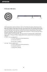
Page 43: ...e purchased as an additional option for non standard products 1 90 days Z AirSpare Service 91 365 days Free Parts and Labor 9 5 EST telephone technical assistance Online technical help Email product u...

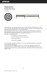
Page 44: ...Standard Warranty expires and the Two Year Extended Warranty begins when the One Year Extended War ranty expires 1 90 days Z AirSpare Service 91 365 days Free Parts and Labor 9 5 EST telephone techni...

Page 45: ...AirSpare Service 91 365 days Free Parts and Labor 9 5 EST telephone technical assistance Online technical help Email product updates Guaranteed One Week Turnaround 2nd year Free Parts and Labor 9 5 ES...

Page 46: ...partment Z Microsys tems at its discretion may offer the AirSpare Service Plan to a customer who purchases a special order item at the one year rate Z Microsystems cannot guarantee next day delivery i...

Page 47: ...Doc 27 0030UM Rev 1 0 Issued 12 04 47 APPENDIX Z Microsystems also provides on site service and consultation to customers who require Z Microsystems technical expertise Z On Site Service...

Page 48: ...without charge If the product is transferred to another user the warranty service is available to that user for the remainder of the warranty period Z Microsystems warranties are voided if the covere...

Page 49: ...hardware fit ted etc 6 System BIOS version number 7 Operating System and version number 8 Display driver version number 9 Video Adapter Type NOTE For image problems run AUTO SETUP again before consult...

Page 50: ...on our products their performance problems found and welcome all constructive suggestions Please send such productive information in writing to Customer Service Z Microsystems 5945 Paci c Center Blvd...

Page 51: ...Z Microsystems Inc 5945 Paci c Center Blvd Suite 505 San Diego CA 92121 Phone 858 657 1000 Fax 858 657 1001 Website www zmicro com Copyright 2005 Z Microsystems Inc All Rights Reserved...

Reviews: