background image

10 


ZTS-100 Z-Thermostat Operations 


The following section will guide you through the set up processes for your ZTS-100.   


Different listening nodes are able to act as repeaters to enlarge the network range.


Please note that all Z-Wave thermostat controllers are designed and manufactured by various 
vendors whom are compatible with your ZTS-100


as long as they carry the Z-Wave logo: 


(Please carefully read through the following then store the manual for future reference.) 


Product Overview 


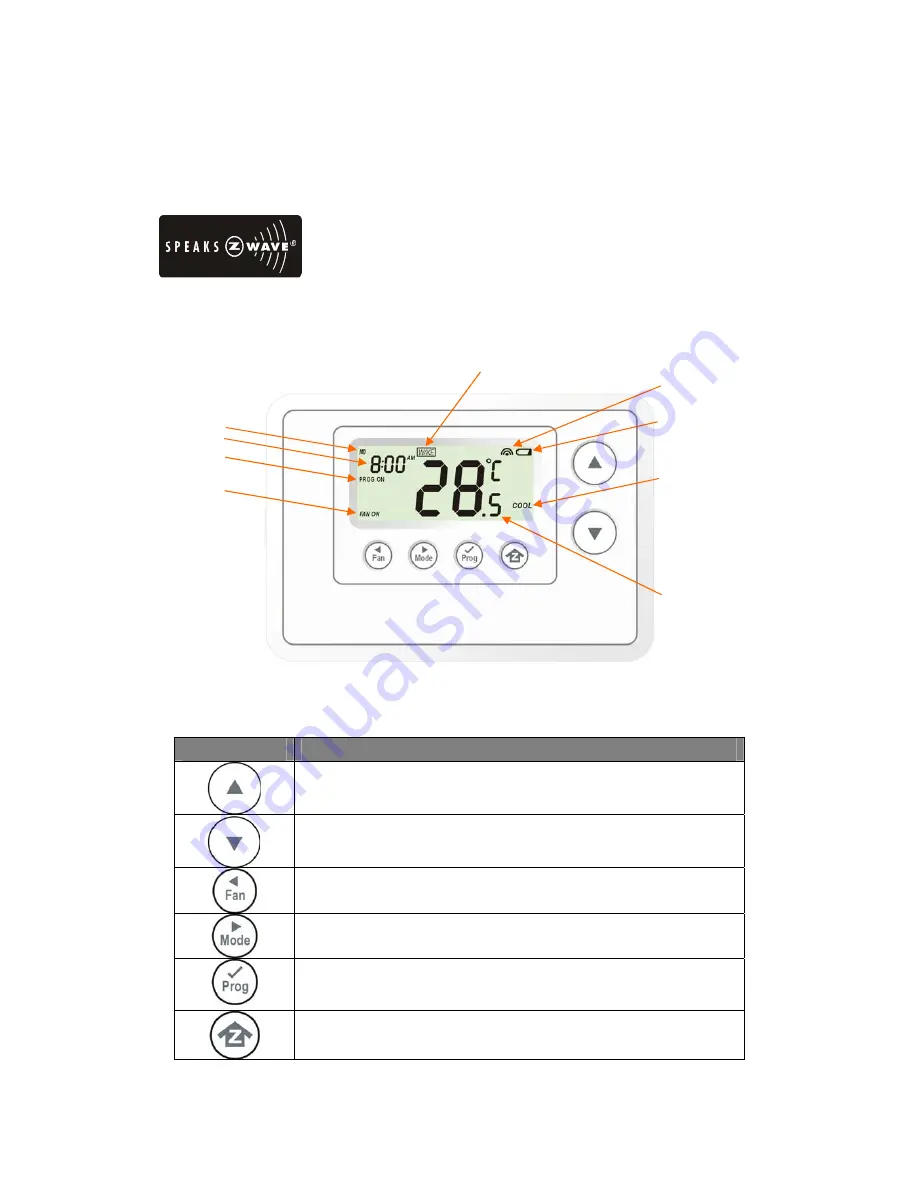
Figure 7. ZTS-100 / ZTS-110 


Description of Function Keys


Symbol 

Key Description 


Increase value / Toggle selection 


Decrease value / Toggle selection 


Select fan mode; also the Backward function key in some menus 


Change operation mode; also the Forward function key in some menus 


Select program mode: 
PROG ON, OVERRIDE and PERMANENT OVERRIDE; 
also the Confirm function key in some menus 


Back to Home 

Battery low indication 

Mode


Program mode 

Fan mode 

Time 

Day 

Inclusion indication


Event mode


Current temperature


Summary of Contents for ZTS-100

Page 1: ...1 ZTS 100 ZTS 110 Z Thermostat ...

Page 2: ... selection for SIMPLE mode 18 Setting Schedule 18 Z Wave Add Inclusion Delete Exclusion Mode 21 Add ZTS 100 to Gateway Controller Z Wave network 22 Delete ZTS 100 from Gateway Controller Z Wave network23 Support Association Command Class 24 Z Wave Configuration Command 25 Filter Counter 26 Reset ZTS 100 to Factory Default Settings 27 Battery Low Indication 28 Defrost Indication 28 Out of Temperatu...

Page 3: ...orld which can go through the Z Wave gateway control ZTS 100 can be configured as either Frequently Listening Routing Slaves FLiRS or Always Listening node and it will distinguish the power source batteries or 24Vac automatically and switch to appropriate mode during inclusion stage FLiRS node type is targeted for battery operated applications and will enter sleep mode frequently in order to conse...

Page 4: ...es heat and cool program settings Temperature Display and Control z Temperature display in F or C z Temperature Measurable Range 32 99 F 0 40 C z Temperature Setting Range 41 99 F 5 37 C z Adjustable Temperature Control Swing Differential a Swing 1 F 2 F 3 F or 4 F 0 5 C 1 0 C 1 5 C or 2 C b Differential 1 F 2 F 3 F or 4 F 0 5 C 1 0 C 1 5 C or 2 C z Advanced Recovery Mode ARM z Defrost Function z ...

Page 5: ...mary Controller The first controller is used to set up your devices and network Only the Primary Controller can be used to include or delete devices from a network It is recommended that you mark the primary controller for each network for ease in modifying your network Secondary Controller A controller containing network information about other devices within the network and is used for controlli...

Page 6: ...ot burn or bury them Installation Location The Thermostat is restricted to be used in indoor only It should be mounted on an inner wall about 1 5m above the floor at a position where it is readily affected by changes of the general room temperature with freely circulating air Avoid mounting above or near hot surfaces or equipment e g TV heater refrigerator Avoid mounting where it will be exposed t...

Page 7: ...connect the RH and RC wire When wiring split systems wire the heating systems 24Vac Power red wire to the ZTS 100 RH terminal and wire the cooling systems 24Vac Power to the ZTS 100 RC terminal Also wire the cooling systems 24Vac Common to the ZTS 100 C terminals Note Do not split RC RH for Heat Pump systems Figure 2 Non heat pump Standard Gas or Electric HVAC system wiring Figure 3 Heat pump syst...

Page 8: ...TH HPUMP and HE HG Jumper Function Description Set to ELECTH for non heat pump system Default Set to HPUMP for heat pump system Set to HG for Gas heat fan controlled unit Default Set to HE for Electrical heat fan controlled unit ...

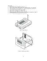
Page 9: ...inside the battery compartment 4 Connect 24Vac power if using 24Vac power source 5 Place the cables at the hole near the terminal block 6 Insert 2 pieces of wall anchors into the holes of the wall 7 Fasten the thermostat with 2 pieces of long screws through the 2 mounting holes Figure 6 8 Install the top housing by hooking the bottom Figure 6 Figure 5 Open ZTS 100 Figure 6 Install the top housing ...

Page 10: ...efully read through the following then store the manual for future reference Product Overview Figure 7 ZTS 100 ZTS 110 Description of Function Keys Symbol Key Description Increase value Toggle selection Decrease value Toggle selection Select fan mode also the Backward function key in some menus Change operation mode also the Forward function key in some menus Select program mode PROG ON OVERRIDE a...

Page 11: ...eration Mode Note 1 In Heat mode it displays HEAT if ELECTH is selected it displays HEAT PUMP if HPUMP is selected Step Procedure Description LCD indication 1 Press Mode key once to change the operation mode OFF HEAT PUMP COOL AUTO OFF ...

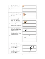
Page 12: ...ly when Cooling is running 2 Press Fan key once to change the Fan mode FAN ON Fan stays on all the time Select Program Mode Step Procedure Description LCD indication 1 Press Prog key once to select PROG mode PROG ON OVERRIDE PERMANENT OVERRIDE PROG ON Run the schedule 2 Press Prog key once to select PROG mode OVERRIDE Temporary override the current schedule and will go back to PROG ON when next ti...

Page 13: ...rmanent Override Note 1 Override Permanent Override is only available in HEAT COOL or AUTO mode Step Procedure Description LCD indication 1 Press Prog key once to select PROG mode OVERRIDE or PERMANENT OVERRIDE at Home page 2 Press Up Down key to adjust set point temperature in HEAT or COOL mode Press Prog key once to confirm the setting or ...

Page 14: ...n key to adjust auto cool set point temperature in AUTO COOL mode Press Prog key once to confirm the setting and go back to Home page Setting Mode set Day Clock 12 24 hour F C Swing and Differential Symbol Setting Mode Key Description Increase value Toggle selection Decrease value Toggle selection Backward to previous setting Forward to next setting Confirm and go to next setting Confirm and go ba...

Page 15: ...t stays in NORMAL mode Press Up Down key to toggle the selection Press Prog key to confirm your settings it will go back to Home page if selected YES it will go to Day setting if selected no SIMPLE mode Active items Change Operation mode Select Fan mode Temperature Scale selection Inactive items Scheduling Program Mode Clock Display Setting Time Setting Swing Setting Differential Set Point Advance...

Page 16: ... setting and it will go to minutes setting Minutes will keep flashing press Up Down key to set minutes 5 Press Prog key once to confirm the setting and it will go to 12 24 hour clock selection Press Up Down key to toggle the 12 24 hour clock selection 6 Press Prog key once to confirm the setting and it will go to temperature F Fahrenheit C Celsius selection Press Up Down key to toggle the temperat...

Page 17: ...o F to 4o F 8 Press Prog key once to confirm the setting and it will go to differential set point setting Press Up Down key to set the differential set point setting Range is from 0 5o C to 2o C or 1o F to 4o F 9 Press Prog key once to confirm the setting and it will go to Advanced Recovery setting Press Up Down key to enable disable Advanced Recovery Mode ...

Page 18: ...ess Up Down key to toggle the temperature F Fahrenheit C Celsius selection Press Prog key to confirm it and back to the Home page Setting Schedule Default Schedule Event Time Heat Cool WAKE 6 00 AM 70 F 21 C 78 F 26 C AWAY 8 00 AM 62 F 17 C 85 F 29 C HOME 6 00 PM 70 F 21 C 78 F 26 C MO FR SLEEP 10 00 PM 62 F 17 C 82 F 28 C WAKE 6 00 AM 70 F 21 C 78 F 26 C AWAY 10 00 AM 62 F 17 C 85 F 29 C HOME 6 0...

Page 19: ...s and hold Prog key for 2 seconds to entry the setting schedule mode Press Up Down key to select MO FR or SA SU schedule 2 Press Prog key once to confirm the setting and it will go to event mode Press Up Down key to select the event WAKE AWAY HOME SLEEP ...

Page 20: ...own key to set minutes 5 Press and hold UP and DOWN key for 2 seconds to disable enable event during the time setting If the event is disabled OFF will be displayed If the event is enabled time will be displayed and Hour will keep flashing 6 Press Prog key once to confirm the setting and it will go to target setting If the event is enabled it will go to target setting Target will keep flashing pre...

Page 21: ...w the program UI to complete the whole scheduling or press Home key once to save and exit Z Wave Add Inclusion Delete Exclusion Mode Symbol Inclusion and Exclusion Mode Key Description N A N A N A N A Add Inclusion Delete Exclusion Back to Home Note 1 This icon is represent the ZTS 100 has been added into the Z Wave network Please perform the Delete Exclusion before adding into the new Z Wave netw...

Page 22: ...Inclusion ZTS 100 to Gateway Controller Z Wave network 4 ZTS 100 will be configured as FLiRS operation after step 3 inclusion ZTS 100 will not response Z Wave command very quickly as it will enter sleep mode frequently in order to conserve battery consumption Application for 24Vac power line 1 Connect 24Vac power and power up the unit make sure AAx4pcs batteries has been removed 2 Execute the step...

Page 23: ... 4 Press Home key once to go back to the home page Delete Exclusion ZTS 100 from Gateway Controller Z Wave network Step Procedure Description LCD indication 1 Gateway Controller device should entry the Exclusion mode Press and hold Home key for 2 seconds to entry the Add Inclusion Delete Exclusion Mode 2 Press Prog key once it will search the network ...

Page 24: ...ups Association group_1 z ZTS 100 will send out basic set command 0xFF automatically once Heat Pump operation has been started in heating mode z ZTS 100 will send out basic set command 0x00 automatically once Heat Pump operation has been stopped in heating mode Association group_2 z ZTS 100 will send out basic set command 0xFF automatically once Compressor operation has been started in cooling mod...

Page 25: ...to 4000 hours resolution 100hrs 4 0x04 Report filter counter read only 0x0000 to 0x270F 0 to 9999 hours 5 0x05 Scale of temperature 0x00 o C 0x01 o F default 6 0x06 Upper limit of set point A A available range Celsius o C A B 2 min 37 0o C max Fahrenheit o F A B 4 min 99 0o F max default 99 0o F 7 0x07 Lower limit of set point B B available range Celsius o C 5 0o C to 35 0o C Fahrenheit o F 41 0o ...

Page 26: ...lace a new filter 3 Press and hold Mode key to set the alert time for the filter usage Target icon will be shown on screen and flashing Press UP or Down to set the alert time Range from 500 to 4000 Hours Step size is 100hrs Press Prog key to confirm the setting and go back to filter counter page Press Home key once to go back to the Home page 4 FILTER icon will be shown on the screen at Home page ...

Page 27: ...confirm the action It will perform the reset if select Yes or It will back to home page if select No LCD display done after reset to factory default settings The following data will be reset to default 1 Clock 12 00am 2 Day Mon 3 Temperature scale F 4 Swing 2F 5 Diff 2F 6 Default schedule 7 Operation mode OFF 8 Default Heat override set point 9 Default Cool override set point 10 Filter counter cle...

Page 28: ...cation 1 DEFROST icon will be displayed at Home page if temperature below 41 F 5 C All heaters will be forced On except in cool mode Out of Temperature Range Indication Step Procedure Description LCD indication 1 HI icon will be displayed on LCD if temperature excess the measurement ranges 99 F 40 C All heaters will be forced Off Cooler will turn on if running cool mode 2 LO icon will be displayed...

Page 29: ...t the temperature to the next program setting When the thermostat is in Advanced Recovery mode the display will show RECOVERY Advanced Recovery is an option that allows the HVAC system to attempt to recover from a setback period and reach a desired comfort temperature set point by the beginning of your programmed comfort period This option allows the choice whether to use Advanced Recovery under S...

Page 30: ... enable disable energy saving mode by using Z Wave BASIC set command only Enable energy saving mode Basic set value 0x00 off mode energy saving mode will be mapped to off mode Disable energy saving mode Basic set value 0xFF resume mode comfort mode will mapped to resume mode ...

Page 31: ...check either the specifications in the manual of your ZTS 100 or also check online at www remotec com hk for a full list of products that can be used with your ZTS 100 All Z Wave products also come with the Z Wave logo Q Can I use 2 or more ZTS 100 in my house What is the max units if yes A Yes and it is very depends on the capability of gateway controller For example gateway can supports up to 8 ...

Page 32: ...and cool set point Example 1 If user select heat set point is 70F the minimum cool set point will be limited at heat set point 4 F 74 F Pervious heat set point is 70 F and cool set point is 74 F Example 2 If user changes heat set point to 72F cool set point will be updated to 76 F automatically to maintain the dead band Set point Temperature Turn off Turn on Off Cool Swing swing Dead band Output H...

Page 33: ...mperature display resolution 0 5 F 0 1 C Temperature Setting range 41 99 F 5 37 C Temperature Operating 32 122 F 0 50 C Storage 23 140 F 5 60 C Dimension L x H x T 145mm x 100mm x 25mm Weight 170g Batteries excluded Z Wave device type Basic Device Class Routing_Slave Enhanced_Lib Generic Device Class Thermostat Specific Device Class Thermostat general v2 Z Wave Command Class Controlled Supported C...

Page 34: ...ee that interference will not occur in a particular installation If this equipment does cause harmful interference to radio or television reception which can be determined by turning the equipment off and on the user is encouraged to try to correct the interference by one or more of the following measures Reorient or relocate the receiving antenna Increase the separation between the equipment and ...

Reviews: