User’s Manual
71
A.1.1 Exclusion Zone
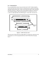
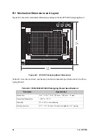
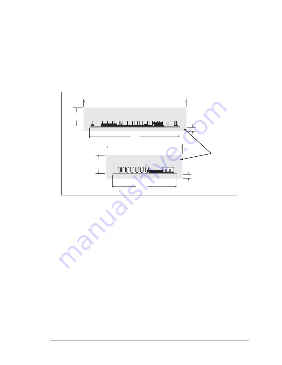
It is recommended that you allow for an “exclusion zone” of 0.25" (6 mm) around the
LP3500 in all directions when the LP3500 is incorporated into an assembly that includes
other printed circuit boards. This “exclusion zone” that you keep free of other components
and boards will allow for sufficient air flow, and will help to minimize any electrical or
electromagnetic interference between adjacent boards. An “exclusion zone” of 0.12"
(3 mm) is recommended below the LP3500. Figure A-2 shows this “exclusion zone.”
Figure A-2. LP3500 “Exclusion Zone”
When using the LP3500 with the Prototyping Board, do not install any components in the
prototyping area on the Prototyping Board between the LP3500 and the Prototyping
Board.
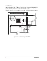
0.70
(18)
4.15
(105)
3.10
(79)
0.70
(18)
Exclusion
Zone
0.12
(3)
0.12
(3)
2.60
(66)
3.65
(93)
Summary of Contents for Fox LP3500
Page 1: ...Fox LP3500 C Programmable Single Board Computer User s Manual 019 0111 041029 E ...
Page 6: ...Fox LP3500 ...
Page 14: ...8 Fox LP3500 ...
Page 22: ...16 Fox LP3500 ...
Page 86: ...80 Fox LP3500 ...
Page 120: ...114 Fox LP3500 ...
Page 130: ...124 Fox LP3500 ...
Page 134: ...128 Fox LP3500 ...
Page 138: ...132 Fox LP3500 ...
Page 142: ...136 Fox LP3500 ...
Page 144: ......

