User’s Manual
37
4.2 Programming Cable
The programming cable has a level converter board in the middle of the cable since the
LP3500 programming port supports CMOS logic levels, and not the higher voltage RS-232
levels that are used by PC serial ports. When the programming cable is connected,
Dynamic C running on the PC can hard-reset the LP3500 and cold-boot it. The cold boot
includes compiling and downloading a BIOS program that stays resident while you work. If
you crash the target, Dynamic C will automatically reboot and recompile the BIOS if it
senses that a target communication error occurred or that the BIOS source code has changed.
4.2.1 Switching Between Program Mode and Run Mode
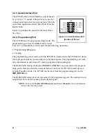
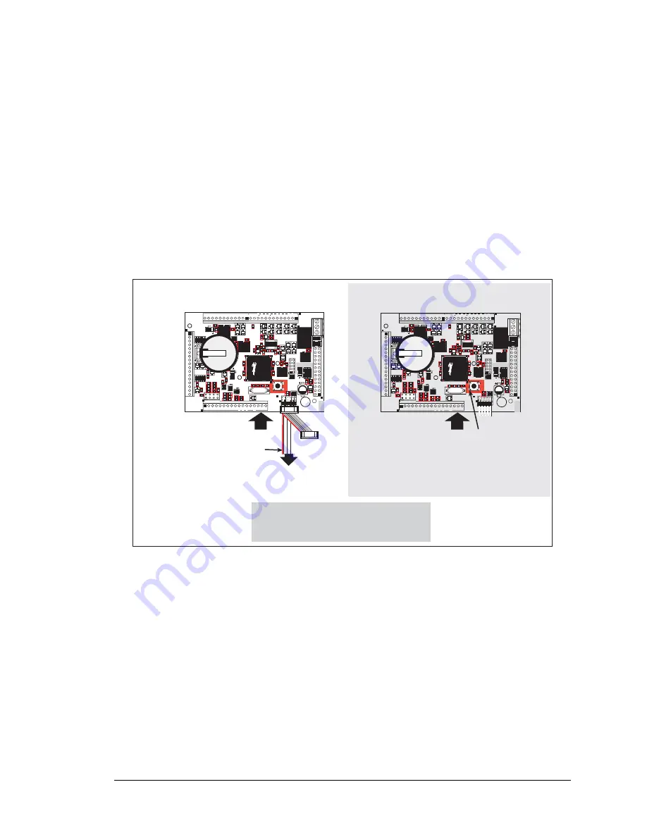
The LP3500 is automatically in Program Mode when the programming cable is attached,
and is automatically in Run Mode when no programming cable is attached. See Figure 19.
Figure 19. LP3500 Program Mode and Run Mode Set-Up
4.2.2 Detailed Instructions: Changing from Program Mode to Run Mode
1. Disconnect the programming cable from header J3 of the LP3500.
2. Reset the LP3500 by unplugging the AC adapter, then plugging it back in, or press the RESET
switch.
The LP3500 is now ready to operate in the Run Mode.
4.2.3 Detailed Instructions: Changing from Run Mode to Program Mode
1. Attach the programming cable to header J1 of the LP3500.
2. Reset the LP3500 by unplugging the AC adapter, then plugging it back in, or press the RESET
switch. Alternatively, you may press
<Ctrl-Y>
on your PC if Dynamic C is running.
The LP3500 is now ready to operate in the Program Mode.
C44
C43
C59
C60
U9
R16
R13
C10
C13
R17
R18
C16
C19
C36
U1
C70
R51
R58
C65
C26 C33
R20 R25
R22 R26
R29
C37
R32
C40
Y1
D22
C50 R36 R40 C54
R37
C24
R30
D19
D20
D21
D18
D25
Q5
R42
Q6
R43
R33
Q8
Q10
D26
D28
Q16
D30
Q17
D34
K1
Q13
D32
D33
Q14
J6
C67
C55 R44
R47
U11
S1
RESET
J5
J2
PROGRAM
PORT
AIN0 AIN1
A
I
N2
AIN3 AIN4 AIN5 AIN6 AIN7 GND
GNDVBAT
EXT GND VIN GND
PWM0
PWM
1
PWM2
GND
DISPLA
Y
R55
R56
J9
J8
RELAY
NO
COM
NC
C48
U3
R57
R31
C29
R23
C22
C20
C12
C15
D15
D17
RP17
D13
BT1
D1
1
D5
D7
D2
D4
C8
C6
D8
D1
AIN0 AIN1 AIN2 AIN3
J3
R1
C3
C2
R6
R7
R9
Q22
RN1
RN2
Battery
R54
RP14
RP13
Q20
U13
C64
R50
R49
Y2
C61
Q12
R45
R34
U8
C51
R39
R41
C53
R38
R48
C66
U12
U10
GND
+K GND 485 + GND TxB RxB GND
TxC RxC GND TxE RxE GND
J4
J1
OUT9
OUT8
OUT7
OUT6
OUT5
OUT4
OUT3
OUT2
OUT0
OUT
1
IN00 IN01 IN02 IN03 IN04 IN05 IN06 IN07
GND
IN08 IN09 IN10 IN1
1 IN12 IN13 IN14 IN15
Power
RESET LP3500 when changing mode:
Press
RESET
switch,
OR
Remove, then reapply power
after removing or attaching programming cable.
Power
Run Mode
Program Mode
Colored edge
Programming
Cable
To
PC
COM
port
DIAG
PROG
RESET
switch
Summary of Contents for Fox LP3500
Page 1: ...Fox LP3500 C Programmable Single Board Computer User s Manual 019 0111 041029 E ...
Page 6: ...Fox LP3500 ...
Page 14: ...8 Fox LP3500 ...
Page 22: ...16 Fox LP3500 ...
Page 86: ...80 Fox LP3500 ...
Page 120: ...114 Fox LP3500 ...
Page 130: ...124 Fox LP3500 ...
Page 134: ...128 Fox LP3500 ...
Page 138: ...132 Fox LP3500 ...
Page 142: ...136 Fox LP3500 ...
Page 144: ......


