User’s Manual
87
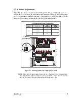
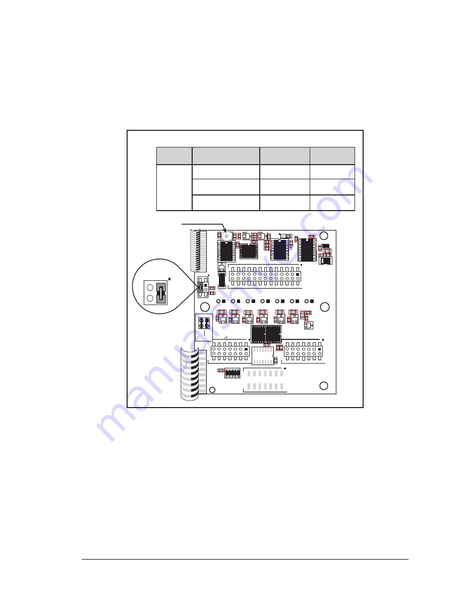
C.2 Contrast Adjustment
Depending on when you acquired your LCD/keypad module, you will be able to set the
contrast on the LCD display by adjusting the potentiometer at R2 or by setting the voltage
for 2.8 V by setting the jumper across pins 1–2 on header J5 as shown in Figure C-3. Only
one of these two options is available on a given LCD/keypad module
Figure C-3. LCD/Keypad Module Contrast Adjustment
NOTE:
Older LCD/keypad modules that do not have a header at J5 or a contrast adjust-
ment potentiometer at R2 are limited to operate only at 5 V, and will not work with the
LP3500. The older LCD/keypad modules are no longer being sold.
C2
R2
R1
C3
D2 C1
D1
C5 U2
JP1
R3
U1
C4
C10
CR1
R6
C13
C12
R7
R8
R25
R26
R11
R13
R14
R10
R9
R12
R15
R18
Q8
R16
Q5
R21
Q2
U5
J2
DISPLAY
BOARD
J4
KP1
R17 Q4
R22
Q6
R23
Q7
R20
Q3 R19
U7 C14
R24 C15
C16
U6
U4
C7
C9
U3
LCD1
C11
R4
R5
C6
J1
Q1
J5
C17
RN1
J5
LP3500
2.8 V
OTHER
3.3 V
1
2
3
4
n.c. = 5 V
LCD/Keypad Module Jumper Configurations
Header
Description
Pins
Connected
Factory
Default
J5
2.8 V
3.3 V
5 V
12
34
n.c.
×
J5
1
2
3
4
Part No. 101-0541
Contrast
Adjustment
Summary of Contents for Fox LP3500
Page 1: ...Fox LP3500 C Programmable Single Board Computer User s Manual 019 0111 041029 E ...
Page 6: ...Fox LP3500 ...
Page 14: ...8 Fox LP3500 ...
Page 22: ...16 Fox LP3500 ...
Page 86: ...80 Fox LP3500 ...
Page 120: ...114 Fox LP3500 ...
Page 130: ...124 Fox LP3500 ...
Page 134: ...128 Fox LP3500 ...
Page 138: ...132 Fox LP3500 ...
Page 142: ...136 Fox LP3500 ...
Page 144: ......

