14
Jackrabbit (BL1800)
2.3.2 Connect Programming Cable
The programming cable connects the Jackrabbit to the PC running Dynamic C to down-
load programs and to monitor the Jackrabbit during debugging.
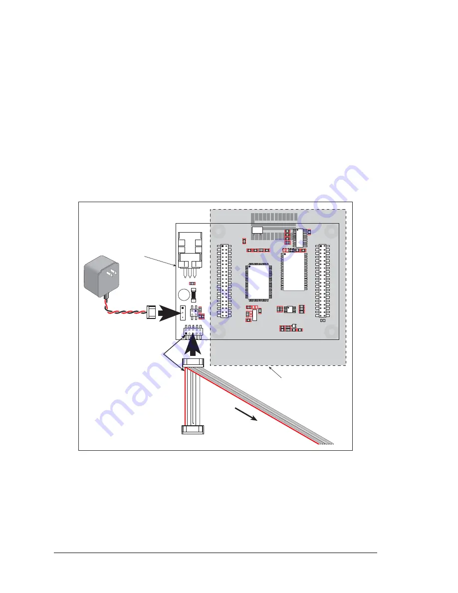
Connect the 10-pin connector of the programming cable labeled
PROG
to header J3 on
the Jackrabbit board as shown in
. Be sure to orient the marked (usually red) edge
of the cable towards pin 1 of the connector. (Do not use the
DIAG
connector, which is used
for a normal serial connection.)
NOTE:
Use only the programming cable that has a red shrink wrap around the RS-232
level converter (Z-World part number 101-0513), which is supplied with the Develop-
ment Kit. Other Z-World programming cables might not be voltage-compatible or their
connector sizes may be different.
Figure 4. Power and Programming Cable Connections
to Jackrabbit Board
Connect the other end of the programming cable to a COM port on your PC.
NOTE:
Some PCs now come equipped only with a USB port. It may be possible to use
an RS-232/USB converter with the programming cable supplied with the Jackrabbit
Development Kit. An RS-232/USB converter is available through the Z-World Web store.
PROTOTYPING BOARD
JACKRABBIT BOARD
JP1
U4
VIN
GND
GND
RESET
JACKRABBIT Z-World, Inc.
GND
PA0
PA2
PA4
PA6
GND
PB0
PB2
PB4
PB6
WDO
GND
PE6
PE4
PE2
PE0
HV0
HV2
K
GND
VCC
PA1
PA3
PA5
PA7
GND
PB1
PB3
PB5
PB7
PCLK
PE7
PE5
PE3
PE1
GND
HV1
HV3
+RAW
VCC
GND
RXC
TXC
PC1
PC3
PC5
PC7
AGND
DA1
PD1
PD3
PD5
PD7
GND
485+
VCC
SM1
STAT
VBAT
GND
VCC
RXB
TXB
PC0
PC2
PC4
PC6
AD0
DA0
PD0
PD2
PD4
PD6
GND
485
VCC
SM0
IOBEN
GND
/RST
J5
U6
U5
U3
J4
U1
J1
J2
J3
Y3
Rabbit 2000
SRAM
RS-232
RS-485
Colored side
lines up with
pin 1
To
PC
COM
port
PROG
DIAG
Programming
connector
Diagnostic
connector
Summary of Contents for Jackrabbit
Page 12: ...8 Jackrabbit BL1800...


