Electronic Loads
-
13-
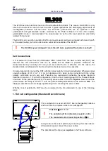
1. Full cell configuration (Standard Kelvin Scheme)
This configuration is used with DUTs like (rechargeable) batteries and fuel cells if a complete cell has
to be investigated. Here, first the sense cables are attached to the DUT with the correct polarity and
then power cables are connected. Since EL1000 is a one quadrant potentiostat so it cannot act as
source but only work as load. Hence it is recommended to use as short and as thick as possible
cables to minimize the resistive losses during operation.
!
Potential
≤
4 V / 100 V
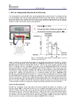
The potential will be indicated as negative in EL
The measured current must be positive I
≥
0
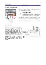
Graph 1: One-Quadrant representation showing battery or fuel cell
connection with the EL1000
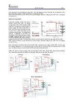
Graph 1 shows the one quadrant representation of the EL1000 connection with the DUT (3 V battery
or fuel cell). In this graph the X-axis represents the
– terminal
of EL1000 and Y-axis represents the
+
terminal
(with the maximum potential limit of 100 V). In part
a
, the anode (negative electrode) of the
DUT is connected with the
– terminal
of EL1000 and is at
system ground
. While the cathode
(positive electrode) is connected to the
+ terminal
of EL1000 (connected to Y-axis via blue line). Here
the potential is positive but it will be indicated as negative in Thales software. In this representation the
current flow is counter clockwise (
current > 0
). EL1000 will read the potential with sense cables
(around DUT – battery) and will always read -3 V. However between the
+
and
– terminals
of the
EL1000, the output potential will be less than 3 V. This decrease (see Graph
1
b
) is due to the voltage
drop
(
V = I*R
)
within the system. This voltage drop depends on the current flowing through the system.
Hence if the current is high then the voltage drop will also be high. When sinking high currents from
low cell potentials (like big single fuel cells) the input potential (at terminal) can become less
than 1 V. In such conditions, the EL1000 will not work properly. Hence when controlling current, keep
in mind that high currents will increase the voltage drop and pay attention to the input potential.
Current setting in EL1000
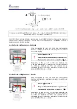
EL1000 has 3 terminals at the back side of the device labelled as positive (
+
), negative (
-
) and
external positive (
EXT +
) terminals. EL1000 is a one quadrant potentiostat and can only work as a
load. So it allows current (
I
) flow only in one direction (clockwise inside EL1000) between its
+
and
–
terminals (see Fig. 01). This means that a DUT (e.g., battery) can only be connected with EL1000 in
one polarity. If that DUT is connected with EL1000 in wrong polarity, the polarity error LED will indicate
this. However, when EL1000 is used with an external power supply via
Ext +
terminal (see chapter 6)
then the current (
i
) can flow in both direction between the
EXT +
and
–
terminals.


