Electronic Loads
-
14-
In EL1000, the
+
terminal is thinner as compared to
–
and
EXT +
terminals because the maximum
allowed current which can flow from
+
terminal is 200 A whereas between
–
and
EXT +
terminals, a
maximum current of 680 A can flow.
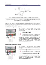
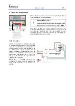
2.a. Half-cell configuration – Cathode
This configuration is used with DUTs like (rechargeable)
batteries and fuel cells if only the cathodic part of the cell has
to be investigated.
!
Potential
≤
4 V / 100 V
The potential will be indicated as negative in EL
The measured current must be positive I
≥
0
Depending on the type of the reference electrode, the
measured potential may be different from the real potential at
the reference electrode site. The real potential can be
calculated from the measured potential by subtracting the
potential of the reference electrode.
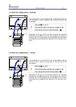
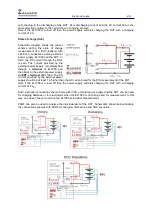
2.b. Half-cell configuration - Anode
This configuration is used with DUTs like (rechargeable)
batteries and fuel cells if only the anodic part of the cell is to be
investigated.
!
Potential
≤
4 V / 100 V
The potential will be indicated as negative in EL
The measured current must be positive I
≥
0
Depending on the type of the reference electrode, the
measured potential may be different from the real potential at
the reference electrode site. The real potential can be
calculated from the measured potential by subtracting the
potential of the reference electrode.
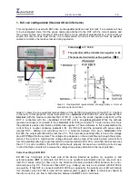
Fig 01: Current flow direction between
+
and
–
terminals and
–
and
EXT +
terminals of EL1000
For ease, we will distinguish the current between the
+
and
–
terminals of EL1000 with
I
and current
between EXT
+
and
–
terminals of EL1000 with
i
.


