Electronic Loads
-
15-
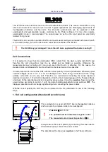
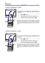
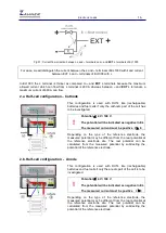
3. Partial cell configuration
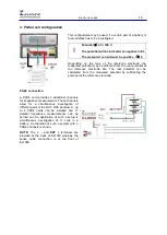
This configuration may be used, if a certain part of a battery or
fuel cell stack has to be investigated.
!
Potential
≤
4 V / 100 V
The potential will be indicated as negative in EL
The measured current must be positive I
≥
0
Depending on the type of the reference electrode, the
measured potential may be different from the real potential at
the reference electrode site. The real potential can be
calculated from the measured potential by subtracting the
potential of the reference electrode.
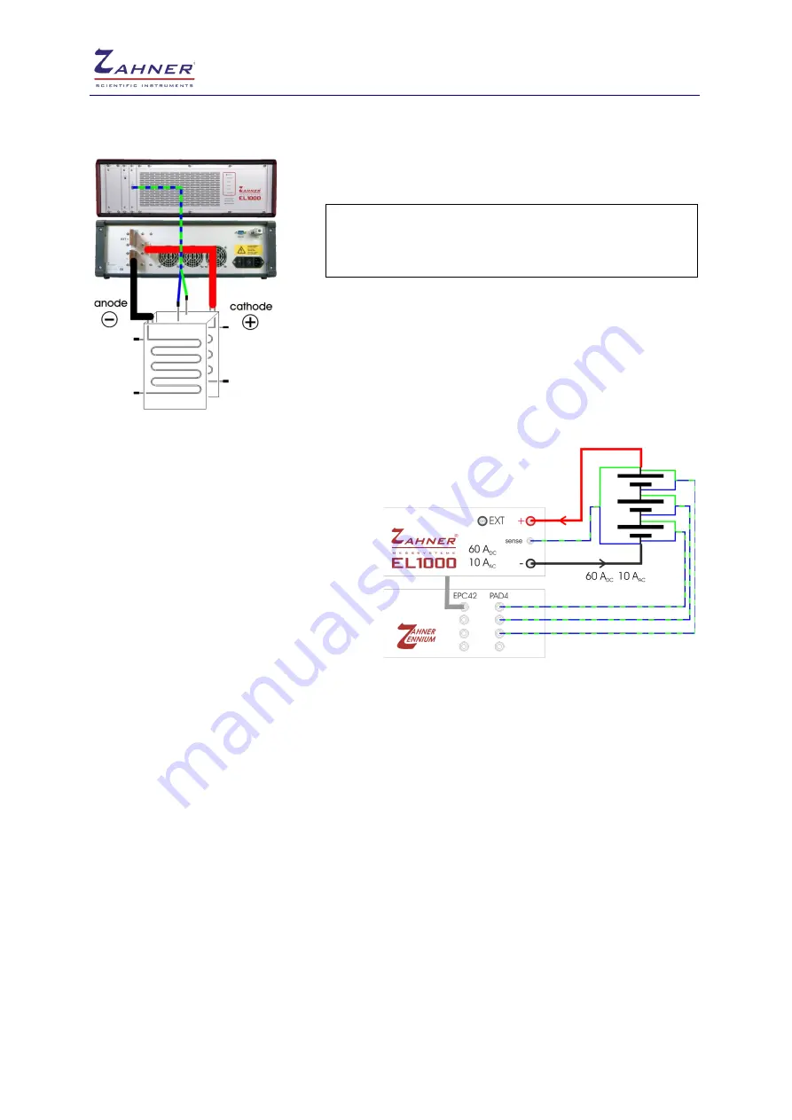
PAD4 connection
A PAD4 card provides 4 additional channels
for impedance measurements. These channels
allow for a simultaneous investigation of
different parts of the DUT. With Zennium X, up
to 4 PAD4 cards can be installed and 17
parallel impedance measurements can be
carried out. An application of such a setup is
simultaneous investigation of 17 cells in a
battery. A schematic of such a system with 3
PAD4 channels is shown.
NOTE:
The
+
,
-
and
EXT +
terminals are
provided at the back of EL1000 whereas the
sense cable connection is at the front of
EL1000.


