Electronic Loads
-
16-
4. Applications with an additional DC load
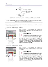
4.a. DUT connected with DC sink and EL1000
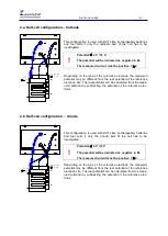
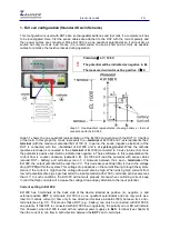
This configuration may be used to sink more current through the DUT than 200A. The total amount of
current from the EL1000 and the additional electronic load must not exceed 680A!
The maximum power dissipation in EL1000 should not increase the EL1000’s limit of 1000 W.
Example:
DUT: Battery of 48 V potential at 210 A
DC
and measure EIS with 5 A amplitude:
EL1000 part of the DC current: 10 A
EL1000 AC amplitude: 5 A
EL1000 power dissipation: 48 V * 15 A = 720 W (<1000 W)
External load DC current: 210 A - 10 A = 200 A
EIS settings in the control potentiostat menu: Galvanostatic, DC current 210A, Amplitude 5A
Note:–
Maximum allowed current through EL1000 in above example = 1000 W / 48 V = 20.8 A
Here PAD4 cards can also be used to investigate the individual cells of a battery or fuel cell. The
potential range of a PAD4 cards is fixed at
±4 V
with the compliance voltage of
±100 V
. Higher input
voltage ranges can be achieved by special sense cables (
±5 V
,
±10 V
,
±12 V
,
±20 V
,
±24 V
). However
!
Potential
≤
4 V / 100 V
The potential will be indicated as negative in EL
There are two current loops and both currents flow through the EL1000 shunt
1) From EL1000 to DUT
2) EL1000 Ext + to 3
rd
party load to DUT
The measured current (total of both current) must be positive I
≥
0
The total current must NOT EXCEED 680 A (max. 200 A from EL1000)
Ensure to switch ON the external load before switching ON EL1000
Ensure to switch OFF EL1000 before switching OFF the external load
During EL1000 startup and calibration do not sink external DC current
EL1000 DC current has to be defined as sum of both currents -> The EL1000 controls the
current through the DUT

