Electronic Loads
-
18-
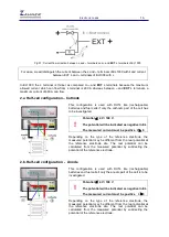
EL1000 and an external load with the DUT. Here the current flowing through the external load (
I
2
)
does not flow through EL1000 and can be independently controlled by the external sink and limitations
from EL1000 do not apply to
I
2
. Since the current flowing through the external load is not flowing
through the
EXT +
terminal of EL1000 hence it is not labelled with
i
but
I
2
.
Resistance box
(R)
in Graph 2 represents the voltage drop in EL1000 current loop during operation.
5. Applications with an additional power supply (serial)
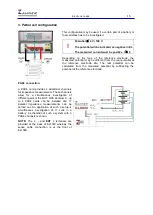
This configuration may be used if the voltage drop on the power lines is too high to reach the high-
current test conditions. In addition it allows experiments on passive objects and batteries under
charging conditions and electrolysis cell. Here EL1000 is connected in series with DUT (inversed
battery) and the external power supply.
5.a. Charging batteries
This configuration is used for experiments on batteries under charging conditions and electrolysis
cells.
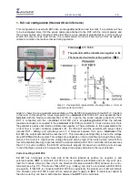
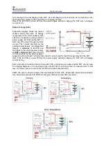
Graph 3 follows the same scheme as described previously in this manual. The X-axis represents the
– terminal
of EL1000 and the Y-axis represents the
+ terminal
of EL1000. Graph 3 (Part
a
) is same
as shown in Graph 1(
a
). As explained in previous graphs that the EL1000 allows current flow in one
direction (counter clockwise) and here this current flow is represented as
I
+
. When EL1000 as a load is
connected with a battery then it discharges the battery. For charging the battery, a reverse current (
I
-
)
should flow through the battery which is not possible with EL1000. Hence to charge a battery during
experiment with EL1000, an external source is required as shown in Graph 3(
b
). This external source
applies a potential against the battery and changes the current direction in the battery, charging it. It
should be noted down here that the potential of the external source should be higher than the battery’s
!
The DC potential applied must not exceed
Umax = 100 V.
Potential
≤
4 V / 100 V
The potential will be indicated as positive in EL
(because the battery connection is reversed
with sense cables)
The measured current must be positive I
≥
0
Graph 3: EL1000 in series connection with a battery and an external source (power supply).


