Electronic Loads
-
22-
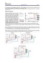
cell), leading to the discharging of the DUT. Here discharging current and the AC current flow in the
same direction contrary to the current flow in charging scheme.
Here if the EL1000 is turned off then the power supply will start charging the DUT with a charging
current of 2 A.
State of charge (SoC)
Schematic diagram shows the current
scheme during the state of charge
measurement of a DUT (battery) with
electrical connections among external
power supply, EL1000 and the DUT. In
SOC, the DC current through the DUT
is zero. The current provided by the
external power supply completely flow
through
+ terminal
of EL1000 and
then back to the external power supply
via
EXT + terminal
of EL1000. The DC
current provided by the external power
supply should be at least 1 A higher than the AC current used for the EIS measurement of the DUT.
Here if the EL1000 is turned off then the power supply will start charging the DUT with a charging
current of 2 A
DC
.
Such a parallel connection scheme among EL1000, external power supply and the DUT can be used
for charging batteries or for electrolysis when the EL1000 is not being used for measurement. In this
way, one doesn’t have to remove the EL1000 setup after measurement.
PAD4 can also be used to analyse the individual part of the DUT. Schematics shown below illustrate
the connection schemes with PAD4 for charging, discharging and SOC scenarios.

