Electronic Loads
-
23-
Built-in buffer amplifier
The built-in buffer amplifier may be used to increase the potential range of the
EL
up to +/-100 V.
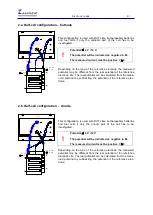
Select the potential range at the cell connection scheme page. The corresponding gain factor will be
set automatically. The
EL1000
will control -4 V...+4 V and -100 V...+100 V.
!
Never plug or unplug an
EL1000
at the D-Sub9 connector at the backside of the
device with the
Zennium
switched on. This may damage the system. It is
recommended to fix the D-Sub9 connector with the screws to prevent accidental
unplugging.
If the
EL1000
is unplugged while being selected in the
Test Sampling
page of the
Thales
software, it
will shut off the current. This is a precaution to prevent undefined situations.
The
EL1000
need a warm-up time of about 15 minutes after power on. A calibration procedure is initi-
ated automatically with the first access by the
Zennium
system. If you access an
EL1000
during the
warm-up time, please do a forced calibration (
EIS
menu ->
Calibrate
) after about 15 minutes.
As the
EL1000
is optimised for high current (some 100 mA to 200 A) an erroneous current display of
some mA is acceptable.
Grounding circuit
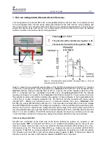
The electrical circuit shown below illustrates the grounding setting of the EL1000. The
– terminal
of
EL1000 is at system ground. And the isolated terminal of EL1000 is connected to the
– terminal
of
EL1000 (system ground) with a 100
Ω
resistance. Capacitor (C
1
) is used to protect the system from
spiked AC signals. For grounding, the isolated terminal is short circuited with the earth ground via a
bridge. In grounding state the – terminal of EL1000 is connected with the grounding via a 100
Ω
resistance. When the bridge is removed then the EL1000 is at floating condition (at system ground).

