Electronic Loads
-
6-
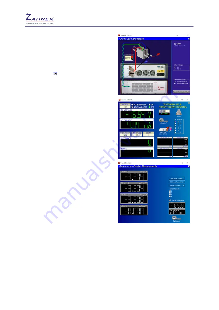
In
check cell connections
, you can set the desired
potential range and choose a reference electrode.
Here for convenience, the EL1000 connection
scheme with the 3
rd
party DC load is also shown.
At the bottom of the page “
Parallel Impedance
Setup
” is provided to setup the PAD4 connections.
Once all the desired settings are complete then click
“
Esc
” or click on to go back to the last window.
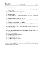
Now connect the sense cables from EL1000 to the
device under test (DUT). Here a battery is used as a
DUT.
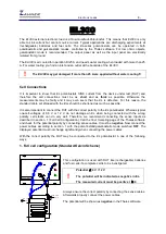
Connect blue sense cable to the
– terminal
and
green sense cable to the
+ terminal
of the DUT. This
will show the correct polarity and a negative potential
will be shown in the
DC VOLTAGE
window.
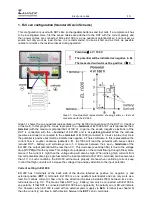
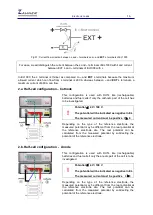
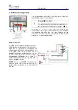
Now connect the power cables for the desired EL1000
arrangement. Please note that with the connection of
the power cables the potential should not change
considerably (connect power cables as shown for
your preferred arrangement in the manual below).
If parallel impedance spectra are to be measured then
click on the “
Parallel Impedance Setup
” in “
Check
Cell Connections
”. This will open a new window
where different channels from the PAD4 cards can be
chosen. Here first 3 channels are selected which are
analysing the individual cell of the DUT (battery).
Also click on “
Enable Impedance
” to allow the
impedance measurement from the PAD4 channels. At
bottom right, the voltage and current from the sense
cables of EL1000 can also be seen.
Changing devices
When changing the device number, the now inactive device will hold its DC conditions such as DC
potential and on/off status as long as it is selected anew or the system is shut off. On the other hand
only the selected device is internally connected to the FRA. Therefore only this device is able to output
an AC signal superimposed to the DC potential.
Potential in electronic loads (EL)
Chemical reactions in the batteries and fuel cells provide us with energy. In the field of
electrochemistry such reactions are shown on a negative potential (energy) scale. However potentials
in the field of electronics and electrical engineering are shown with a positive sign. Hence to facilitate
the chemists in comparing the reactions and carrying out different experiments, the potential’s reading
in electronic loads (EL) is reversed. e.g., if one measure a potential of a battery by a voltmeter and it
reads +2 V then the EL300/EL1000 will read it as -2 V.


