RESERATOR XT
RESERATOR XT
5.3 Reserator XT
’
s Coolant Circulation
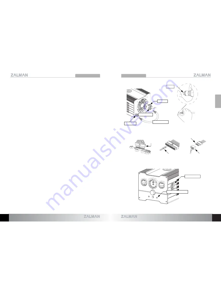
1) The purpose of connecting the Jump Cable of the Power Supply
’
s Main Connector
(20P/24P) is to receive direct current (12V) needed for the test run and leakage
inspection.
2) For smooth initial degassing, connect one end of the Degassing Tube to the OUT
terminal of the Reserator, and repeatedly press the opposite Quick Coupling end - with
the finger to discharge the internal air. Now remove this end of the Degassing Tube
from the OUT terminal.
3) Connect the other end of the Degassing Tube to the IN terminal and remove the
internal air in the method described above, and connect the opposite Quick Coupling
end to the OUT terminal.
4) Remove the Power Supply
’
s Main Connector (20P/24P) and the 4-Pin CPU
Sub
Connector from the motherboard, and connect the Green Wire Terminal and Black
Wire Terminal of the Main Connector (20P/24P) with the provided Jump Cable.
5) Connect the DC Cable to the Power Terminal on the Reserator XT
’
s back panel, and
connect the opposite 4-Pin Connector to the Power Supply
’
s 4-Pin Connector.
6) Supplying power to the Power Supply will light up the Red LED on the front panel,
cause the Flow Indicator
’
s Impeller to rotate, and the Blue LED on the side panel to
light up. For discharging of the gas within the Reserator and good coolant circulation,
turn the Power Supply ON/OFF approximately 3~7 times in 10 second intervals.
7) Circulate the coolant for approximately 10 minutes for leakage inspection and for
checking its operation, then turn OFF the Power Supply. Disconnect the Degassing
Tube, and disassemble the Quick Coupling Inserts from the Degassing Tube.
Note 1) Make sure that the coolant of the Reservoir does not overflow when tilting the unit.
Note 2) Check the degassing status by looking at the tubes. Once degassing is complete, turn the
PC OFF and install the Water Blocks.
Note 3) If the Flow Indicator detects a problem with coolant circulation, an alarm will sound and the
red LED will begin to flicker. Press the Light/Reset button for 5 seconds to restart the
system.
English
9
•
The specifications of this product and its components may change without prior notice to improve performance.
10
•
The specifications of this product and its components may change without prior notice to improve performance.
4-Pin Connector
DC Cable
Main
Connector
M/Board
Jump Cable
DC Cable
OUT Terminal
Degassing Tube
IN Terminal
PUSH
LED/Reset Button
Flow indicator
Summary of Contents for Reserator XT
Page 1: ...English Version...


