www.zalman.co.kr www.zalmanusa.com 41
TNN 500A
English
9.4 Connecting Cables
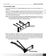
1. Connect the power cables to the HDD/ODD/Motherboard/ Graphics Card and the data cables to the
HDD/ODD.
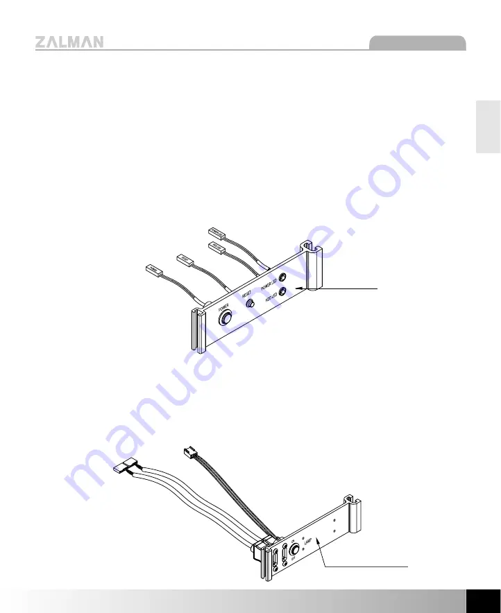
2. Refer to the motherboard installation manual and insert the Switch Panel connectors into the correct
jumper pins on the motherboard.The Switch Panel’s Power LED uses a 3-pin connector by default : if
the motherboard requires a 2-pin connector, replace the Switch Panel connector accordingly (a 2-pin
connector is included with the product).
Note)
1) Each of the switch Panel’s connectors have labels indicating which jumper pins to connect the to.
2) Unscrewing the Right Heatsink Plate’s bolts (PH M4X12) counterclockwise by one turn enables
the panel’s location to be adjusted or completely disassemble.
3. Refer to the motherboard installation manual and connect the USB lines to the USB extension header
and the LED Lamp’s 3-pin connector to the motherboard’s 3-pin fan header. Opening the TNN 500A’s
Front and Back Door and turning the LED Lamp switch on will let you see the USB’s working state by light.
Note)
Unscrewing the Right Heatsink Plate’s bolts (PH M4X12) counterclockwise by one turn enables the
panel’s location to be adjusted or completely disassembled.
Switch Panel
USB & LED Lamp Panel

