background image

(0,5s)

(0,5s)

(0,5s)

(0,5s)

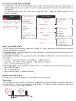
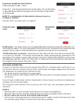
4. Assign buttons to selected modes.

5. When selecting partial opening of a gate, specify “Delay time” (1 s - 300 s with 1s increment).

6. To display the transmitter view with the assigned button numbers, press

“Transmitter view”.

7. Press the “Save” button, the transmitter is remotely programmed with the receiver. If the set-

tings are saved correctly, a message “the devices are paired” is displayed.

NOTE: The value of “Delay time” assigned to a button for partial opening of a gate may 

be different from the value set in the configuration window of the corresponding ROB-21 

channel.

The delay time is assigned individually to the button.

REMOVING ASSIGNED REMOTE CONTROL BUTTONS USING APPLICATION

1. Select “Configure” from the ROB-21 menu.

2. Select “Assigned transmitters”.

3. The device will display a list of all buttons assigned to the channel.

4. To remove assigned button, select “remove” (or drag the item to the left).

5. Confirm the action.

6. Device will display a message confirming deletion of assigned button.

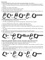
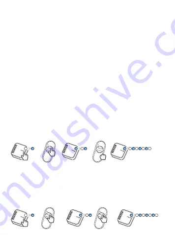
ASSIGNING REMOTE CONTROL BUTTONS USING PROG BUTTON

Single pulse

1. Press the PROG button briefly (0.5s) - STATUS LED lights up blue (programming channel 1 

button). To assign the button to the second channel, wait about 5 s until the STATUS LED lights 

up red.

2. Press and hold the remote control button you want to assign for the channel.

3. STATUS LED will turn off and then light up again.

4. Release the remote control button.

5. After the button has been correctly assigned, the STATUS LED will flash 3 times and the con-

troller will exit the programming mode.

Partial opening of a gate

1. Press the PROG button briefly (0.5s) - STATUS LED lights up blue (programming channel 1 

button). To assign the button to the second channel, wait about 5 s until the STATUS LED lights 

up red.

2. Press briefly the remote control button you want to assign to a channel.

3. STATUS LED will turn off and then light up again.

4. Press briefly the remote control button again.

5. After the button has been correctly assigned, the STATUS LED will flash 3 times and the con-

troller will exit the programming mode.

Summary of Contents for exta life ROB-21

Page 1: ...leży składować w miejscach do tego przeznaczonych Elektrośmieci pochodzące z gospodarstwa domowego można oddać bezpłatnie i w dowolnej ilości do utworzonego w tym celu punktu zbierania a także do sklepu przy okazji dokonywania zakupu nowego sprzętu ZAMEL Sp z o o niniejszym oświadcza że typ urządzenia radiowego ROB 21 jest zgodny z dyrektywą 2014 53 UE Pełny tekst deklaracji zgodności UE jest dost...

Page 2: ... x 5A 250 VAC Liczba zacisków przyłączeniowych 8 przewody o przekroju do 2 5 mm2 Sposób montażu puszka Ø60 mm pogłębiona kieszeniowa Temperaturowy zakres pracy 10 do 55 C Stopień ochrony obudowy IP20 Wymiary 47 5 x 47 5 x 20 mm Waga 0 04 kg OPIS Odbiornik ROB 21 przeznaczony jest do otwierania zamykania bram wjazdowych lub garażo wych z poziomu pilotów oraz aplikacji EXTA LIFE Odbiornik można równ...

Page 3: ...racę urządzenia lub dopro wadzić do jego uszkodzenia Czynności związane z podłączeniem oraz regulacją powinny być wykonane przez wykwalifiko wanego elektryka ze względów bezpieczeństwa nie należy montować urządzenia bez obudowy lub z uszkodzoną obudową Do instalacji należy użyć wkrętaka krzyżowego do 3 5 mm Zaciski śrubowe umożliwiają podłączenie przewodu maksymalnie 2 5 mm Podany w instrukcji zas...

Page 4: ...ia Sterowanie dwoma bramami wjazdowymi krańcówki do sygnalizacji otwarcia Krańcówka brama zamknięta Krańcówka brama 1 zamknięta Krańcówka brama 1 otwarta Krańcówka brama 2 zamknięta Krańcówka brama 2 otwarta Krańcówka brama otwarta Sterowanie lokalne bramy Sterowanie lokalne bramy 2 Sterowanie lokalne bramy 2 Sterowanie lokalne bramy 1 Sterowanie lokalne bramy 1 Elektro zaczep BRAMA 1 BRAMA 1 BRAM...

Page 5: ...symalnie 60 s Jeżeli odbiornik zostanie znaleziony to możesz wcześniej zakończyć wyszukiwanie poprzez naciśnięcie przycisku Zatrzymaj Po wyszuka niu odbiornik będący w zasięgu kontrolera automatycznie pojawi się na liście wraz z domyślną nazwą ROB 21 6 cyfrowy numer seryjny ID 3 Naciśnij przycisk TEST umożliwi to szybką lokalizację odbiornika W przypadku ROB 21 podczas testu wyjścia są włączane na...

Page 6: ...nkcja krańcówki parametr określa jaką funkcję pełni krańcówka podłączona do danego wejścia Zamknięcie krańcówka sygnalizuje zamknięcie bramy furtki Otwarcie krańcówka sygnalizuje otwarcie bramy furtki Brak krańcówka niepodłączona Typ krańcówki parametr określa rodzaj krańcówki podłączonej do danego wejścia NO krańcówka normalnie otwarta NC krańcówka normalnie zamknięta W celu zapisania ustawień na...

Page 7: ...ycisku pilota lub przycisku z poziomu apli kacji najpierw generowany jest impuls o długości określonej przez parametr Czas impulsu Po jego zaniku odliczany jest czas określony przez parametr Czas opóźnienia i ponownie automatycznie generowany jest impuls o długości określonej przez parametr Czas impulsu UWAGA Dodatkowy impuls jest generowany tylko wówczas gdy skonfigurowane są krańcówki przynajmni...

Page 8: ...lu ponownego wyszukania i sparowania z kontrolerem należy zresetować ROB 21 do ustawień fabrycznych Tryb bramy z funkcją furtki Uchylanie bramy aktywne Czas opóźnienia czas liczony pomiędzy pierwszym a drugim impul sem Drugi impuls jest generowanym automatycznie jeżeli brama przed pierwszym impulsem była zamknięta UWAGA wymagana wcześniejsza konfiguracja krańcówek przynaj mniej jedna jako Zamknięc...

Page 9: ...innymi pilotami działającymi na częstotliwości 868 MHz Piloty radiowe mogą być wpisywane poprzez aplikację lub za pomocą przycisku PROG Tryb przypisany dla wybranego przycisku pilota może być różny od trybu w jakim kanał jest widoczny z poziomu aplikacji EXTA LIFE WPISYWANIE PRZYCISKÓW PILOTA POPRZEZ APLIKACJĘ Czynności wstępne 1 Zainstaluj kontroler EFC 01 2 Dodaj urządzenie ROB 21 do kontrolera ...

Page 10: ... element w lewo 5 Potwierdź chęć usunięcia wskazanego przycisku 6 Usunięcie zostanie potwierdzone komunikatem WPISYWANIE PRZYCISKÓW PILOTA POPRZEZ PRZYCISK PROG Pojedynczy impuls 1 Naciśnij na krótko 0 5s przycisk PROG dioda STATUS zaświeci się na niebiesko progra mowanie przycisku do kanału 1 Jeżeli chcesz wpisać przycisk do drugiego kanału odczekaj około 5s aż dioda STATUS zaświeci się na czerwo...

Page 11: ...ż dioda STATUS zaświeci na kolor cyjan 3 Naciśnij na krótko przycisk pilota który wcześniej wpisałeś w trybie uchylania bramy 4 Na krótko zostanie wysterowane wyjście do którego jest wpisany przycisk Dioda STATUS zacznie migać z interwałem 1 s 5 Po czasie który chcesz ustawić maksymalnie 300 s powtórnie naciśnij przycisk pilota 6 Na krótko zostanie wysterowane wyjście dioda STATUS zamruga 3 razy i...

Page 12: ...w EFC 01 z softem począwszy od v1 6 0 pliki aktualizacyjne pobierane są automatycznie z internetu W celu aktualizacji oprogramowania w odbiorniku 1 Z poziomu menu kontekstowego wybierz Informacje o wersji 2 Jeżeli jest dostępna aktualizacja to przycisk Aktualizuj będzie oznaczony kolorem czerwo nym 3 Naciśnij przycisk Aktualizuj 4 Po około 5s odbiornik przejdzie do procesu aktualizacji sygnalizuje...

Page 13: ...ce should be stored in designated areas For this purpose you can dispose of household waste free of charge and in any quantity to a collection point set up as well as to the shop when you buy new equipment Hereby ZAMEL Sp z o o declares that the radio equipment type ROB 21 is in compliance with Directive 2014 53 EU The full text of the EU declaration of conformity is available at the following int...

Page 14: ...ption 95 5 mA for 12 V AC 64 1 mA for 24 V AC 58 6 mA for 12 V DC 29 9 mA for 24 V DC Transmission power ERP 20 mW Transmission radio 868 MHz 868 5 MHz ISM band Method of transmission two way 9600 bps Coding algorithm based on 128 bit key Range up to 200 m in the open area Optic signalling of device operation yes STATUS LED Maximum number of paired buttons 96 pairs over 2 channels Information on t...

Page 15: ...vice s operation or damage it Connection and configuration operations should be carried out by a qualified electrician For safety reasons do not install the unit without casing or with damaged casing To install the device use a cross head screwdriver with 3 5 mm diameter The screw terminals allow to connect a wire with a cross section of 2 5 mm2 The range specified in the manual up to 200m is rele...

Page 16: ...g two entrance gates limit switches signalling opening Limit switch gate 1 closed Limit switch gate 1 opened Limit switch gate 2 closed Limit switch gate 2 opened Local gate 2 control Local gate 2 control Local gate 1 control Local gate 1 control CONNECTION GATE 1 GATE 1 GATE 2 GATE 2 Button PEDESTRIAN GATE GATE Limit switch gate closed Limit switch gate opened Local gate control Electric strike ...

Page 17: ...ximum of 60 seconds If the receiver is found you can end the search earlier by pressing the Stop button Once found a receiver within range of the controller will automatically appear on the list with the default name ROB 21 6 digit serial ID number 3 Press the TEST button this will allow you to quickly locate the receiver During testing ROB 21 its outputs are activated for approximately 1s and the...

Page 18: ...nnel 2 Limit switch function this parameter defines the function of the limit switch connected to the given input Closing limit switch signals closing of gate pedestrian gate Opening limit switch signals opening of gate pedestrian gate None limit switch not connected Limit switch type this parameter defines the type of limit switch connected to the given input NO NO limit switch NC NC limit switch...

Page 19: ...g the remote control button or the button in the applica tion a pulse of the duration defined by the Pulse time parameter is generated After it disappears the time specified by the Delay time parameter is set and a pulse of the duration specified by the Pulse time parameter is automatically generated again NOTE Additional pulse is generated only if the limit switches are configured at least one se...

Page 20: ...controller again ROB 21 must be reset to its factory settings Gate mode pedestrian gate function Partial opening of a gate active Delay time time between the first and second pulse The second pulse is automatically generated if the gate was closed before the generation of the first pulse NOTE Pre configuration of limit switches at least one set on Closing is required Set time from 1 s to 300 s wit...

Page 21: ...68 MHz Radio remote controllers can be assigned using the application or by using the PROG button The mode assigned to a selected remote control button may be different from the mode of a channel visible in the EXTA LIFE application ASSIGNING REMOTE CONTROL BUTTONS USING APPLICATION Preliminary activities 1 Install EFC 01 controller 2 Add ROB 21 device to the controller 3 Add the remote control to...

Page 22: ... Device will display a message confirming deletion of assigned button ASSIGNING REMOTE CONTROL BUTTONS USING PROG BUTTON Single pulse 1 Press the PROG button briefly 0 5s STATUS LED lights up blue programming channel 1 button To assign the button to the second channel wait about 5 s until the STATUS LED lights up red 2 Press and hold the remote control button you want to assign for the channel 3 S...

Page 23: ...econds for the STATUS LED to light up cyan 3 Briefly press the remote control button you previously assigned to partial opening of a gate mode 4 The output to which the button is assigned will be activated briefly STATUS LED will flash at 1 s intervals 5 After setting time maximum 300 s press the remote control button again 6 The output will be activated the STATUS LED will flash 3 times and the r...

Page 24: ...e context menu In case of EFC 01 controllers from version v1 6 0 update files are downloaded automatically from the Internet To update the receiver s software 1 Select Version from the context menu 2 If an update is available the Update button will be red 3 Press the Update button 4 After approx 5s the receiver starts the update STATUS LED flashes green 5 The update takes about 1 minute and is com...

Reviews: