ADDING CAMERAS
RECORDING SETTINGS
By standard, the cameras included in the system are already paired with the recorder. Therefore, no additional steps need to be taken
to add them. However, if, for any reason, the cameras are not displayed on the list of devices or if additional cameras are added (offered
by Zamel as product with the symbol: ZMB-01/C), program each camera for the recorder by following the instructions below:
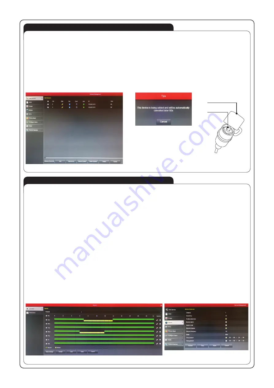
• In the main menu, select the “Camera” option to open the “Camera management” window” and display the list of cameras installed
in the system (Fig. 11).
• Next, click on the “Wireless code Add” to display the notification in Fig. 12 signaling that the 120 sec. programming procedure was
started.
• Find the programming button on the incoming cable connected to the camera. If it is secured with a cap, remove it to gain access to
the button (Fig. 13).
• Next, press the programming button for about 6 sec. until 3 LEDs on the camera front start to blink. After a few seconds from releas-
ing the button, the new camera should appear on the list of available devices in the recorder. Use this method to add subsequent
cameras (as part of the 120 sec. programming procedure). If all cameras are not programmed in 120 sec., call the programming
function from the recorder’s menu again.
9 cameras in total can be programmed for the recorder.
Click on the main icon “Record” to access settings used to configure the mode, in which the camera is to operate (continuous operation,
motion detection) and the time, in which the camera is to operate (days of the week, hours). Fig. 14.
By default, the system is set to continuous operation on all channels (cameras), meaning that the recorder will record image from all
cameras non-stop.
This can be done by distributing green or yellow rectangles depending on the day of the week (column) and hour (row). A green rectan-
gle means that image will be recorded at the specified hour. A yellow rectangle means that image will be recorded at the specified hour
only when movement is detected. When both continuous recording and motion-sensing are set for a specified hour (green and yellow
rectangle), 2 films will be recorded - one as scheduled and one when motion is detected.
All schedule settings are made either for all cameras at the same time (select the “All” option in the “channel” field) or for individual
cameras independently (select the channel number [camera], to which the schedule setting will apply, in the “channel” field).
If the motion detection function is used, perform an additional configuration of individual cameras in the following manner:
• in the main menu, select the “Camera” option,
• in the open window, select the “Motion” tab (Fig. 15),
• select the channel (camera), to which this setting applies, in the “Channel” field,
• select the motion detection sensitivity (0-10) in the “Sensitivity” field,
• check the “Enable detection” box,
• if motion detection is to initiate a voice signal, check the “Voice alarm” box,
• if motion detection is to initiate a procedure to send a notification e-mail, check the “Send e-mail” box,
• check the “Record channel” box,
• determine the time, for which the recorder is to record image after motion is detected, in the “Recording time” field,
• determine the day of the week, on which motion detection is to be active (if motion detection is to be active on all days, select “All”)
in the “Day of the week” field,
• check the “Period 1” and set the time from 00:00 to 24:00,
• apply the changes by clicking on “Apply”.
The settings can be automatically copied to other cameras (channels), using the “Copy” function.
Fig.11
Fig.14
Fig.15
Fig.12
Fig.13
Protective
cap
Programming
key


