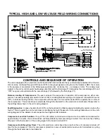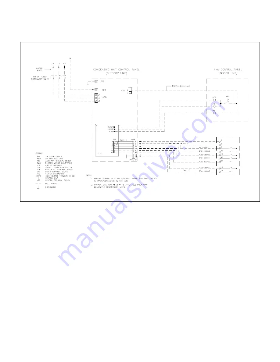
TYPICAL HIGH AND LOW VOLTAGE FIELD WIRING CONNECTIONS
17
CONTROLS AND SEQUENCE OF OPERATION
The unit is equipped with an electronic control board which can be linked with any commercially available 24V ac thermo-
stat or can be controlled through a DDC panel. With cooling input signals coming from a thermostat or DDC, the motors
in the equipment are started in the following sequential order: condenser fan – compressor motor. The cooling input
signals to the unit’s control board should always start first with the first stage (Y1) followed by the second stage (Y2) and
“OFF” sequence should start with the second stage (Y2) followed by the first stage (Y1).
Balance Loading of Compressors:
The user can select the sequence of operation of the compressors; either com-
pressor 1 as always leading (dip switch #2 set at ON) or enabling balance loading of compressor (dip switch #2 set at
OFF). In balance loading function, the compressor with the least run time will be started first to equalize the run time of
the compressors. These functions are selectable through the dip switch on the electronic control board. Please refer to
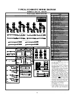
the settings table shown in the unit’s wiring diagram.
Fault Diagnostics:
In case of system fault, LED’s on the board emits a flashing signal indicating the nature or where the
fault is. This is to guide the service technician in identifying the fault. Please refer to the settings table shown in the unit’s
wiring diagram for the details of each respective fault against LED indicators.
Compressor Lock-Out Function:
If any of the unit’s safety control devices trips and such condition is maintained for
approximately 3 minutes, the control will lock-out that particular system preventing a re-start. It can be re-set by shutting
off power to the thermostat or if the cooling signal to the board is turned OFF.
Compressor Anti-Recycling Timer:
The unit’s electronic control board has a built-in three (3) minutes minimum off
timer for the compressor. This is for compressor protection in case of accidental manual re-set or immediate re-cycling
through the thermostat due to load demand.
FROM T'STAT CONTROLLER OR DDC
SWITCHING CONTACTS
Summary of Contents for Cooline CDL Series
Page 8: ...7 DIMENSIONS NOTE All dimensions are in mm CDL 020 CDL 025 CDL 030 CDL 035 CDL 040 ...
Page 9: ...8 DIMENSIONS NOTE All dimensions are in mm CDL 050 CDL 055 CDL 065 ...
Page 11: ...10 DIMENSIONS NOTE All dimensions are in mm CDL 135 CDL 160 ...
Page 12: ...11 DIMENSIONS NOTE All dimensions are in mm CDL 195 ...


